Difference between revisions of "Getting Started with RFNoC Development"
m (→Adding custom blocks to OOT Module) |
(Emphasize that this application is deprecated) |
||
| (38 intermediate revisions by 7 users not shown) | |||
| Line 1: | Line 1: | ||
==Application Note Number== | ==Application Note Number== | ||
| − | |||
| + | '''AN-823''' | ||
| + | <!-- Internal use only: please do keep this updated! | ||
==Revision History== | ==Revision History== | ||
{| class="wikitable" | {| class="wikitable" | ||
| Line 18: | Line 19: | ||
|style="text-align:center;"| Added “Digital Gain” example | |style="text-align:center;"| Added “Digital Gain” example | ||
|- | |- | ||
| + | |||
| + | |- | ||
| + | |style="text-align:center;"| 2017-05-08 | ||
| + | |style="text-align:center;"| Jose Loera | ||
| + | |style="text-align:center;"| Updated example code. Update to Testbench section. | ||
| + | |- | ||
| + | |||
| + | |- | ||
| + | |style="text-align:center;"| 2017-08-26 | ||
| + | |style="text-align:center;"| Jose Loera | ||
| + | |style="text-align:center;"| Updated following sections: '''Abstract'''(This AN is specific to USRP X300/X310), '''Using a graphical interface'''(updated GUI image with newest version and the explanation section), '''Testing out the custom block'''(Updated GRC image that has correct Sampling Rate for RFNoC:Radio block). | ||
| + | |- | ||
| + | |||
| + | |- | ||
| + | |style="text-align:center;"| 2017-09-07 | ||
| + | |style="text-align:center;"| Jose Loera | ||
| + | |style="text-align:center;"| Added link to Video that follows this App Note in the Resources section. Also [https://youtube.com/watch?v=j-EfyPVpaJ8 here] | ||
| + | |- | ||
| + | |||
| + | |- | ||
| + | |style="text-align:center;"| 2019-10-24 | ||
| + | |style="text-align:center;"| Michael Dickens | ||
| + | |style="text-align:center;"| Fixed list of USRPs that this AN is applicable to: all current 3rd generation USRP hardware. | ||
| + | |- | ||
| + | |||
|} | |} | ||
| + | --> | ||
==Abstract== | ==Abstract== | ||
| − | This application note guides a user through basic information on the RFNoC architecture, installing necessary software to develop custom RFNoC blocks, also called Computation Engines (CE), and walks through the steps of creating a custom RFNoC block using an example. | + | '''Note: This application note is DEPRECATED. It applies only to using RFNoC in UHD 3.x. The latest Getting Started in RFNoC application note is available here: [[Getting Started with RFNoC in UHD 4.0]].''' |
| + | |||
| + | This application note guides a user through basic information on the RFNoC architecture, installing necessary software to develop custom RFNoC blocks, also called Computation Engines (CE), and walks through the steps of creating a custom RFNoC block using an example. RFNoC is currently supported on any 3rd generation USRP hardware, currently: E310/E312, E320, N300/N310/N320/N321, and X300/X310. '''However''', this document primarily covers using RFNoC for the USRP X300/X310 and E310/E312. Using RFNoC with the other USRPs is similar to that documented herein. | ||
==Overview== | ==Overview== | ||
| Line 27: | Line 56: | ||
==Licensing== | ==Licensing== | ||
| − | The RFNoC code base is open source, including code that executes on the host, as well as code targeted to the USRP hardware (FPGA and microcontroller firmware). | + | The RFNoC code base is open source, including code that executes on the host, as well as code targeted to the USRP hardware (FPGA and microcontroller firmware). RFNoC is available under the open-source GNU Lesser General Public License (LGPL). For more information on our licensing policy, please contact [mailto:[email protected] [email protected]]. |
==Prerequisites== | ==Prerequisites== | ||
| − | RFNoC is only supported on | + | RFNoC is only supported on 3rd generation USRP hardware as noted in the Abstract. |
In order to build custom USRP FPGA images and RFNoC blocks the following hardware and software are needed. | In order to build custom USRP FPGA images and RFNoC blocks the following hardware and software are needed. | ||
| Line 36: | Line 65: | ||
* '''Ubuntu 14.04.5 or 16.04.1 (preferred):''' Currently PyBOMBS (which can be used to install the ''Software build tools''), works most reliably in Ubuntu, and thus, we recommend using this distribution. Also, a majority of the scripts used during the build process are Linux (Ubuntu) specific. A PC with multiple cores and 8GB+ of RAM is recommended. | * '''Ubuntu 14.04.5 or 16.04.1 (preferred):''' Currently PyBOMBS (which can be used to install the ''Software build tools''), works most reliably in Ubuntu, and thus, we recommend using this distribution. Also, a majority of the scripts used during the build process are Linux (Ubuntu) specific. A PC with multiple cores and 8GB+ of RAM is recommended. | ||
| − | * '''Xilinx Vivado tools (version | + | * '''Xilinx Vivado tools (version 2017.4):''' The specific version depends on the branch and state of the FPGA code. The default install location is <code>/opt/Xilinx/Vivado</code>. Once all of the Software build tools are installed the specific version for the downloaded code can be found in the <code>setupenv.sh</code> file located in the <code>{USER_PREFIX}/src/uhd-fpga/usrp3/top/{DEVICE}</code> directory. Further information can be found [http://files.ettus.com/manual/md_usrp3_build_instructions.html here]. |
* '''Software build tools:''' If UHD can be or has been compiled from source on the development PC then all the necessary software build components are present (PyBOMBS can be used to set all this up and instructions on how to do so are given in a following step). | * '''Software build tools:''' If UHD can be or has been compiled from source on the development PC then all the necessary software build components are present (PyBOMBS can be used to set all this up and instructions on how to do so are given in a following step). | ||
| − | * | + | * Any 3rd generation USRP hardware as noted in the Abstract. |
'''NOTE:''' | '''NOTE:''' | ||
| Line 62: | Line 91: | ||
===Create development environment using PyBOMBS=== | ===Create development environment using PyBOMBS=== | ||
| − | The cleanest way to set this up is to install everything into a dedicated directory. [ | + | The cleanest way to set this up is to install everything into a dedicated directory. [https://github.com/gnuradio/pybombs PyBOMBS] is the simplest way to do this. If not already installed, PyBOMBS can be setup with the following commands: |
$ sudo apt-get install git | $ sudo apt-get install git | ||
| Line 252: | Line 281: | ||
At the end of a successful compilation process, write the new image to a USRP. If the image was compiled for a USRP X310, the following command will load the new image. Update the <code>{IP_Address}</code> of the USRP and <code>{USER_PREFIX}</code> to the appropriate values for your configuration before running the command. | At the end of a successful compilation process, write the new image to a USRP. If the image was compiled for a USRP X310, the following command will load the new image. Update the <code>{IP_Address}</code> of the USRP and <code>{USER_PREFIX}</code> to the appropriate values for your configuration before running the command. | ||
| − | $ uhd_image_loader --args | + | $ uhd_image_loader --args "type=x300,addr={IP_ADDRESS}" --fpga-path {USER_PREFIX}/src/uhd-fpga/usrp3/top/x300/build/usrp_x310_fpga_RFNOC_HG.bit |
'''NOTE:''' FPGA images are specific to the USRP device '''NOT''' the USRP series. For example, a USRP X300 FPGA image will '''NOT''' work on a USRP X310 and vice versa. Loading an image that does not correspond to a USRP device will likely brick the device. Additional instructions on flashing a custom image to a device can be found [http://files.ettus.com/manual/page_usrp_x3x0.html#x3x0_load_fpga_imgs here] for X3xx series and [http://files.ettus.com/manual/page_usrp_e3x0.html#e3x0_load_fpga_imgs here] for E3xx series. | '''NOTE:''' FPGA images are specific to the USRP device '''NOT''' the USRP series. For example, a USRP X300 FPGA image will '''NOT''' work on a USRP X310 and vice versa. Loading an image that does not correspond to a USRP device will likely brick the device. Additional instructions on flashing a custom image to a device can be found [http://files.ettus.com/manual/page_usrp_x3x0.html#x3x0_load_fpga_imgs here] for X3xx series and [http://files.ettus.com/manual/page_usrp_e3x0.html#e3x0_load_fpga_imgs here] for E3xx series. | ||
| Line 300: | Line 329: | ||
* You always need a <code>Device3</code> object in your flow graph (it does not get connected, see screenshot below). | * You always need a <code>Device3</code> object in your flow graph (it does not get connected, see screenshot below). | ||
| − | * You should have at least two RFNoC blocks connected together | + | * You should have at least two RFNoC blocks connected together. Going <code>GNU Radio Block</code> -> <code>RFNoC Block</code> -> <code>GNU Radio Block</code> is not recommended (it will work, but with suboptimal performance). |
The GNU Radio flowgraph <code>rfnoc_ddc.grc</code> is an example that can be run using the default RFNoC image. Below are screenshots of the flowgraph and what it produces. | The GNU Radio flowgraph <code>rfnoc_ddc.grc</code> is an example that can be run using the default RFNoC image. Below are screenshots of the flowgraph and what it produces. | ||
| Line 306: | Line 335: | ||
[[File:rfnoc gsg an 1.png|center|800px|]] | [[File:rfnoc gsg an 1.png|center|800px|]] | ||
| − | '''NOTE:''' Copy Block: In the RFNoC domain, streams of data can not be split as easily as they are in the GNU Radio domain. The “copy” block depicted in the screenshot above serves the function as a stream splitter . | + | '''NOTE:''' Copy Block: In the RFNoC domain, streams of data can not be split as easily as they are in the GNU Radio domain. The “copy” block depicted in the screenshot above serves the function as a stream splitter. Its main purpose, when “enabled”, is to copy the samples it is getting at its input and put them into the output, but here it is also serving as a boundary between a RFNoC-domain and a GNURadio-domain. In the flowgraph above, after this boundary is passed, the data stream can easily be split into the two sinks to have them run simultaneously (standard GNU Radio functionality). It is possible to connect the GNU Radio blocks directly to RFNoC blocks without a “copy” block, but only one would work at a time (the other ones would have to be disabled). Another way to split data streams from the RFNoC-domain is to use the ”RFNoC: split stream” block, which would split the streams in the RFNoC domain, but this is not very useful here as we are, in any case, moving into the GNURadio-domain. |
[[File:rfnoc gsg an 2.png|center|800px|]] | [[File:rfnoc gsg an 2.png|center|800px|]] | ||
| Line 380: | Line 409: | ||
Block/code identifier: gain | Block/code identifier: gain | ||
Enter valid argument list, including default arguments: | Enter valid argument list, including default arguments: | ||
| − | |||
| − | |||
Block NoC ID (Hexadecimal): 1111222233334444 | Block NoC ID (Hexadecimal): 1111222233334444 | ||
Skip Block Controllers Generation? [UHD block ctrl files] [y/N] N | Skip Block Controllers Generation? [UHD block ctrl files] [y/N] N | ||
| Line 389: | Line 416: | ||
The following is a description of the valid argument list items: | The following is a description of the valid argument list items: | ||
| − | |||
| − | |||
| − | |||
| − | |||
* '''NoC ID:''' This ID is a Hexadecimal number which serves as identification between the hardware part and the software part of the design. It can be as long as 16 0-9 A-F digits. If a NoC ID is not provided, it will be set to a random number. | * '''NoC ID:''' This ID is a Hexadecimal number which serves as identification between the hardware part and the software part of the design. It can be as long as 16 0-9 A-F digits. If a NoC ID is not provided, it will be set to a random number. | ||
| Line 477: | Line 500: | ||
[[File:rfnoc gsg an 8.png|center|800px|]] | [[File:rfnoc gsg an 8.png|center|800px|]] | ||
| − | Open the file <code>rfnoc-tutorial/rfnoc/fpga-src/noc_block_gain.v</code> that contains the RFNoC block skeleton code that was created when the <code>$ rfnocmodtool add gain</code> command was run and modify the following | + | Open the file <code>rfnoc-tutorial/rfnoc/fpga-src/noc_block_gain.v</code> that contains the RFNoC block skeleton code that was created when the <code>$ rfnocmodtool add gain</code> command was run and modify the following ('''BOLD''' indicates changes to the skeleton code). |
| − | + | ||
| − | + | ||
'''localparam [7:0] SR_GAIN = SR_USER_REG_BASE;''' | '''localparam [7:0] SR_GAIN = SR_USER_REG_BASE;''' | ||
| Line 498: | Line 519: | ||
endcase | endcase | ||
end | end | ||
| + | |||
| + | '''wire [31:0] pipe_in_tdata;''' | ||
| + | '''wire pipe_in_tvalid, pipe_in_tlast;''' | ||
| + | '''wire pipe_in_tready;''' | ||
| + | |||
| + | '''wire [31:0] pipe_out_tdata;''' | ||
| + | '''wire pipe_out_tvalid, pipe_out_tlast;''' | ||
| + | '''wire pipe_out_tready;''' | ||
| + | |||
| + | '''// Adding FIFO to ensure Pipeline''' | ||
| + | '''axi_fifo_flop #(.WIDTH(32+1))''' | ||
| + | '''pipeline0_axi_fifo_flop (''' | ||
| + | '''.clk(ce_clk),''' | ||
| + | '''.reset(ce_rst),''' | ||
| + | '''.clear(clear_tx_seqnum),''' | ||
| + | '''.i_tdata({m_axis_data_tlast,m_axis_data_tdata}),''' | ||
| + | '''.i_tvalid(m_axis_data_tvalid),''' | ||
| + | '''.i_tready(m_axis_data_tready),''' | ||
| + | '''.o_tdata({pipe_in_tlast,pipe_in_tdata}),''' | ||
| + | '''.o_tvalid(pipe_in_tvalid),''' | ||
| + | '''.o_tready(pipe_in_tready));''' | ||
| + | |||
| + | '''wire [15:0] i = pipe_in_tdata[31:16];''' | ||
| + | '''wire [15:0] q = pipe_in_tdata[15:0];''' | ||
| + | |||
| + | '''wire [31:0] i_mult_gain = i*gain;''' | ||
| + | '''wire [31:0] q_mult_gain = q*gain;''' | ||
| + | |||
| + | '''wire [31:0] mult_gain = {i_mult_gain[15:0], q_mult_gain[15:0]};''' | ||
| + | '''axi_fifo_flop #(.WIDTH(32+1))''' | ||
| + | '''pipeline1_axi_fifo_flop (''' | ||
| + | '''.clk(ce_clk),''' | ||
| + | '''.reset(ce_rst),''' | ||
| + | '''.clear(clear_tx_seqnum),''' | ||
| + | '''.i_tdata({pipe_in_tlast,mult_gain}),''' | ||
| + | '''.i_tvalid(pipe_in_tvalid),''' | ||
| + | '''.i_tready(pipe_in_tready),''' | ||
| + | '''.o_tdata({pipe_out_tlast,pipe_out_tdata}),''' | ||
| + | '''.o_tvalid(pipe_out_tvalid),''' | ||
| + | '''.o_tready(pipe_out_tready));''' | ||
| + | |||
| + | '''/* Output Signals */''' | ||
| + | '''assign pipe_out_tready = s_axis_data_tready;''' | ||
| + | '''assign s_axis_data_tvalid = pipe_out_tvalid;''' | ||
| + | '''assign s_axis_data_tlast = pipe_out_tlast;''' | ||
| + | '''assign s_axis_data_tdata = pipe_out_tdata;''' | ||
| + | The following is a block diagram of the code created by the above Verilog: | ||
| − | + | [[File:gain_block_diagram_v01.png|center|800px|]] | |
| − | + | '''NOTE:''' In order to meet timing, FIFO blocks were added to either side of the Multiplication process. | |
| − | + | ||
| − | + | ||
| − | + | ||
| − | + | ||
| − | + | ||
| − | + | ||
| − | + | ||
| − | + | ||
| − | + | ||
| − | + | ||
| − | + | ||
| − | + | ||
| − | + | ||
| − | '''NOTE:''' | + | |
===Creating and running HDL testbenches=== | ===Creating and running HDL testbenches=== | ||
| − | In order to make the coding iteration process more efficient, it is recommended to create testbenches for all RFNoC blocks before compiling them into the FPGA image. This allows for flaw and/or bug detection early in the design. RFNoC Modtool provides the structure and files ( e.g. | + | In order to make the coding iteration process more efficient, it is recommended to create testbenches for all RFNoC blocks before compiling them into the FPGA image. This allows for flaw and/or bug detection early in the design. RFNoC Modtool provides the structure and files ( e.g. noc_block_{USER_BLOCK_NAME}_tb ) for the testbenches of each of the OOT blocks that are added with the <code>$ rfnocmodtool add</code> command. |
| − | Below is a figure that shows the | + | Below is a figure that shows the general testbench architecture that is created by the RFNoC Modtool. This architecture allows a user to test their custom block in the exact same environment it will be placed in when it is built into the RFNoC architecture. Other benefits of the testbench architecture include: |
| + | * Testing through multiple blocks (e.g. FILTER -> FFT -> AVE) | ||
| + | * Testing with multiple streams (e.g. RFNoC block ADD/SUB takes 2 streams, one that will have a constant added to it and one that will have a constant subtracted from it) | ||
| + | * Data transfer abstraction (e.g. RFNoC Sim Lib API calls to <code>tb_streamer.send</code> and <code>tb_streamer.recv</code> which take care of all the AXI stream signaling) | ||
[[File:rfnoc gsg an 9.png|center|800px|]] | [[File:rfnoc gsg an 9.png|center|800px|]] | ||
| + | |||
| + | '''NOTE:''' The <code>noc_block_tb</code> block is an instantiation of the <code>noc_block_export_io</code> that is used in testbenches to communicate to the RFNoC architecture. This makes it possible to talk “RFNoC” to the user’s custom block and as such the custom block has a complete RFNoC experience (signaling, flowcontrol, addressing, etc) | ||
From the [[Getting Started with RFNoC Development#Adding_custom_blocks_to_OOT_Module|Adding custom blocks to OOT Module section]] where the <code>gain</code> block was initially created, the last files generated were: | From the [[Getting Started with RFNoC Development#Adding_custom_blocks_to_OOT_Module|Adding custom blocks to OOT Module section]] where the <code>gain</code> block was initially created, the last files generated were: | ||
| Line 540: | Line 599: | ||
* <code>noc_block_gain_tb.sv:</code> this is a ''System Verilog'' file, in which user custom tests are to be located. This is the '''only''' file that needs to be modified. | * <code>noc_block_gain_tb.sv:</code> this is a ''System Verilog'' file, in which user custom tests are to be located. This is the '''only''' file that needs to be modified. | ||
* <code>Makefile:</code> This file determines the directives that run the simulation. | * <code>Makefile:</code> This file determines the directives that run the simulation. | ||
| + | |||
| + | |||
| + | The <code>noc_block_gain_tb.sv</code> testbench skeleton code creates the following architecture: | ||
| + | |||
| + | [[File:testbench_arch_gain_v01.png|center|800px|]] | ||
Open the file <code>rfnoc-tutorial/rfnoc/testbenches/noc_block_gain_tb/noc_block_gain_tb.sv</code> and modify the following lines: | Open the file <code>rfnoc-tutorial/rfnoc/testbenches/noc_block_gain_tb/noc_block_gain_tb.sv</code> and modify the following lines: | ||
| + | |||
| + | Right under the “Verification” section: | ||
initial begin : tb_main | initial begin : tb_main | ||
| Line 548: | Line 614: | ||
logic [63:0] readback; | logic [63:0] readback; | ||
'''logic [15:0] gain;''' | '''logic [15:0] gain;''' | ||
| + | |||
| + | In the “Test 4 -- Write / readback user registers” section: | ||
`TEST_CASE_START("Write / readback user registers"); | `TEST_CASE_START("Write / readback user registers"); | ||
random_word = $random(); | random_word = $random(); | ||
| − | '''tb_streamer.write_user_reg(sid_noc_block_gain, noc_block_gain.SR_GAIN, random_word[15:0]); | + | '''tb_streamer.write_user_reg(sid_noc_block_gain, noc_block_gain.SR_GAIN, random_word[15:0]);''' |
| − | tb_streamer.read_user_reg(sid_noc_block_gain, 0, readback); | + | '''tb_streamer.read_user_reg(sid_noc_block_gain, 0, readback);''' |
| − | $sformat(s, "User register 0 incorrect readback! Expected: %0d, Actual %0d", readback[15:0], random_word[15:0]); | + | '''$sformat(s, "User register 0 incorrect readback! Expected: %0d, Actual %0d", readback[15:0], random_word[15:0]);''' |
| − | `ASSERT_ERROR(readback[15:0] == random_word[15:0], s);''' | + | '''`ASSERT_ERROR(readback[15:0] == random_word[15:0], s);''' |
| − | + | ||
| + | In the “Test 5 -- Test sequence” section: | ||
| + | |||
`TEST_CASE_START("Test sequence"); | `TEST_CASE_START("Test sequence"); | ||
'''gain = 100;''' | '''gain = 100;''' | ||
'''tb_streamer.write_user_reg(sid_noc_block_gain, noc_block_gain.SR_GAIN, gain);''' | '''tb_streamer.write_user_reg(sid_noc_block_gain, noc_block_gain.SR_GAIN, gain);''' | ||
| − | + | fork | |
| − | begin | + | begin |
| − | + | cvita_payload_t send_payload; | |
| − | + | for (int i = 0; i < SPP/2; i++) begin | |
| − | + | send_payload.push_back(64'(i)); | |
| − | + | end | |
| − | + | tb_streamer.send(send_payload); | |
| + | end | ||
| + | begin | ||
| + | cvita_payload_t recv_payload; | ||
| + | cvita_metadata_t md; | ||
| + | logic [63:0] expected_value; | ||
| + | tb_streamer.recv(recv_payload,md); | ||
| + | for (int i = 0; i < SPP/2; i++) begin | ||
| + | '''expected_value = i*gain;''' | ||
| + | |||
| + | Test #4 verifies that we can write and readback the <code>gain</code> value. Test #5 writes to the <code>gain</code> register, sends a sample set in the form of a ramp (1, 2, 3, 4, etc) to the RFNoC gain block and finally reads the values from the <code>gain</code> block and compares them to expected values. The followings steps will allow the user to run this testbench. | ||
| − | + | From within the <code>rfnoc-tutorial</code> directory, create a <code>build</code> directory and enter it by running: | |
$ mkdir build && cd build/ | $ mkdir build && cd build/ | ||
| Line 672: | Line 751: | ||
====Discussion on FPGA image targets==== | ====Discussion on FPGA image targets==== | ||
| − | RFNoC target names follow the pattern <code>{DEVICE} | + | RFNoC target names follow the pattern <code>{DEVICE}_RFNOC_{BUILD_TYPE}</code> with the following build types: |
* <code>HG:</code> 1GigE on SFP+ Port0, 10Gig on SFP+ Port | * <code>HG:</code> 1GigE on SFP+ Port0, 10Gig on SFP+ Port | ||
| Line 840: | Line 919: | ||
'''NOTE:''' There is a restriction on the amount of blocks that can added into the FPGA image, see the section in this Application Note labeled [[Getting_Started_with_RFNoC_Development#Discussion_on_number_of_blocks_in_an_FPGA_image|Discussion on number of blocks in an FPGA image]] for more information. | '''NOTE:''' There is a restriction on the amount of blocks that can added into the FPGA image, see the section in this Application Note labeled [[Getting_Started_with_RFNoC_Development#Discussion_on_number_of_blocks_in_an_FPGA_image|Discussion on number of blocks in an FPGA image]] for more information. | ||
| − | <code>-I INCLUDE_DIR:</code> The <code>-I</code> directive provides the path to the users <code>rfnoc/fpga-src</code> directory which contains the custom blocks. This path is needed by the Xilinx Vivado tool. Inside the <code>fpga-src</code> directory there is a file called <code>Makefile.srcs</code> that contains the path of the OOT module and a list of all the custom OOT blocks. This is an auto generated file, which is amended every time a new block is added to the OOT module. Manually modifying this file is not recommended. If there are multiple OOT modules with various custom blocks that reside in different directories the way to include them all is by separating the different paths by a space (e.g. <code>-I /first/OOT/path/ /second/OOT/path/</code>) | + | <code>-I INCLUDE_DIR:</code> The <code>-I</code> directive provides the path to top OOT directory, which contains the users <code>rfnoc/fpga-src</code> directory which contains the custom blocks. This path is needed by the Xilinx Vivado tool. Inside the <code>fpga-src</code> directory there is a file called <code>Makefile.srcs</code> that contains the path of the OOT module and a list of all the custom OOT blocks. This is an auto generated file, which is amended every time a new block is added to the OOT module. Manually modifying this file is not recommended. If there are multiple OOT modules with various custom blocks that reside in different directories the way to include them all is by separating the different paths by a space (e.g. <code>-I /first/OOT/path/ /second/OOT/path/</code>). |
| + | |||
| + | '''IMPORTANT:''' Please be sure to terminate the path of your OOT with the "/" character. Otherwise the path might not be recognized. | ||
<code>-d DEVICE:</code> The <code>-d</code> directive directs the script on which USRP device the build is for. If no <code>–d</code> is included the default is <code>–d x310</code>. Generation-3 USRPs and above all support RFNoC. | <code>-d DEVICE:</code> The <code>-d</code> directive directs the script on which USRP device the build is for. If no <code>–d</code> is included the default is <code>–d x310</code>. Generation-3 USRPs and above all support RFNoC. | ||
| Line 859: | Line 940: | ||
$ cd {USER_PREFIX}/src/uhd-fpga/usrp3/tools/scripts | $ cd {USER_PREFIX}/src/uhd-fpga/usrp3/tools/scripts | ||
| − | $ ./uhd_image_builder.py gain ddc fft -I {USER_PREFIX}/src/rfnoc-tutorial | + | $ ./uhd_image_builder.py gain ddc fft -I {USER_PREFIX}/src/rfnoc-tutorial/ -d x310 -t X310_RFNOC_HG -m 6 --fill-with-fifos |
At the end of a successful compilation process, write the new image to a USRP. The following command will load the new image. Update the <code>{IP_Address}</code> of the USRP and <code>{USER_PREFIX}</code> to the appropriate values for your configuration before running the command. | At the end of a successful compilation process, write the new image to a USRP. The following command will load the new image. Update the <code>{IP_Address}</code> of the USRP and <code>{USER_PREFIX}</code> to the appropriate values for your configuration before running the command. | ||
| − | $ uhd_image_loader --args | + | $ uhd_image_loader --args "type=x300,addr={IP_ADDRESS}" --fpga-path {USER_PREFIX}/src/uhd-fpga/usrp3/top/x300/build/usrp_x310_fpga_RFNOC_HG.bit |
'''NOTE:''' | '''NOTE:''' | ||
| Line 925: | Line 1,006: | ||
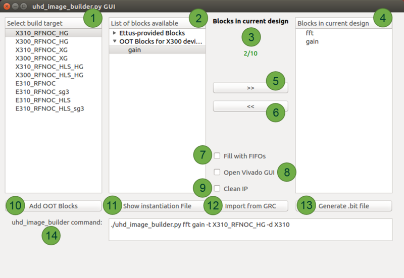
'''2. List of blocks available:''' In this panel the available blocks are listed that can be included into a custom design. This list separates the RFNoC blocks provided by Ettus Research and the OOT modules and corresponding blocks that the user adds. Given the hardware differences between the X3xx and E3xx devices, this list will dynamically change when a different device is selected from the panel on the left. This implies that it is necessary to add the OOT modules for each device independently. This is accomplished by using the <code>Add OOT Blocks</code> feature of the application, details of which are explained at #7 (<code>Add OOT Blocks</code>). | '''2. List of blocks available:''' In this panel the available blocks are listed that can be included into a custom design. This list separates the RFNoC blocks provided by Ettus Research and the OOT modules and corresponding blocks that the user adds. Given the hardware differences between the X3xx and E3xx devices, this list will dynamically change when a different device is selected from the panel on the left. This implies that it is necessary to add the OOT modules for each device independently. This is accomplished by using the <code>Add OOT Blocks</code> feature of the application, details of which are explained at #7 (<code>Add OOT Blocks</code>). | ||
| − | '''3. Blocks in current design:''' This | + | '''3. Blocks in current design:''' This section gives information on the MAX number of blocks for a given USRP (based on the target selection). There is a maximum number of blocks that can be added for each device. See the section in this App Note labeled "Discussion on number of blocks in an FPGA image" for more information. |
| − | '''4. | + | '''4. Blocks in current design:''' This panel will be populated by adding elements from the available blocks. All the blocks listed in here will be compiled into the FPGA custom image. There is a maximum number of blocks that can be added for each device. See the section in this App Note labeled "Discussion on number of blocks in an FPGA image" for more information. |
| − | '''5. | + | '''5. Add button (>>):''' Manually add the blocks from the central panel into your design. |
| − | '''6. | + | '''6. Remove button (<<):''' Remove blocks from the current design (far-left panel) |
| − | '''7. | + | '''7. Fill with FIFOs:''' By checking this box, the design will fill any available/unspecified block slots with FIFOs. The number of FIFO blocks that will be instantiated is based on the rules of amount of blocks explained at #3. When less than the max amount of blocks are needed for certain implementation, many users choose to fill their design with FIFO blocks. |
| − | '''8. | + | '''8. Open Vivado GUI:''' Open Vivado GUI during the FPGA building process. This allows the user to save a Vivado project with all IP and work within the Vivado GUI for development. |
| − | '''9. | + | '''9. Clean IP:''' Cleans the IP before a new build (recompiles all IP). |
| − | '''10. | + | '''10. Add OOT blocks:''' Manually add RFNoC Modtool-generated OOT modules by pointing the application to the <code>Makefile.srcs</code> file, which is located in the <code>{USER_PREFIX}/src/{USER-OOT-moddir}/rfnoc/fpga-srcs/</code> directory. After adding this file, blocks will appear under “<code>OOT blocks for XXXX devices</code>” |
'''11. Show Instantiation File:''' The application auto-generates the instantiation file that is going to be used by Vivado to build the FPGA image. This instantiation file can be viewed and edited before starting the build by clicking this button. | '''11. Show Instantiation File:''' The application auto-generates the instantiation file that is going to be used by Vivado to build the FPGA image. This instantiation file can be viewed and edited before starting the build by clicking this button. | ||
| − | '''12. Generate .bit file:''' Start the build by clicking this button. | + | '''12. Import from GRC:''' If the user has a GNU Radio flowgraph with RFNoC blocks already in it, this application can read what RFNoC blocks are in the flowgraph and populate the <code>Blocks in current design</code> section of the application with the necessary RFNoC blocks. '''NOTE:''' All RFNoC blocks pulled from a <code>.grc</code> file must be in the of <code>List of blocks available</code> before beginning the build. |
| + | |||
| + | '''13. Generate .bit file:''' Start the build by clicking this button. | ||
| + | |||
| + | '''14. uhd_image_builder command:''' The command line command with arguments is dynamically build here as the user selects different options. The user could save this command to use next time they build/compile an FPGA image to avoid having to select all options again. | ||
'''NOTE:''' See the latter end of the previous section for additional information on what to expect once the compile has started as well as final output. | '''NOTE:''' See the latter end of the previous section for additional information on what to expect once the compile has started as well as final output. | ||
| Line 1,015: | Line 1,100: | ||
GNU Radio is built around the concept of blocks, similarly to RFNoC. When mapping RFNoC into an application, the simple constraint is made that every RFNoC block maps to a single GNU Radio block. Thus, when creating mixed GNU Radio/RFNoC applications, there is a very clear 1:1 mapping between what’s happening in RFNoC and GNU Radio. | GNU Radio is built around the concept of blocks, similarly to RFNoC. When mapping RFNoC into an application, the simple constraint is made that every RFNoC block maps to a single GNU Radio block. Thus, when creating mixed GNU Radio/RFNoC applications, there is a very clear 1:1 mapping between what’s happening in RFNoC and GNU Radio. | ||
| − | Since most RFNoC blocks behave very similar to one another from GNU Radio’s perspective, it is generally not required to write C++ code for another block. Rather, a default block provided by RFNoC can be used with appropriate configuration. However, in some cases it may be desirable or even necessary to write a custom GNU Radio block for more specific controlling of the underlying RFNoC block. GNU Radio allows writing blocks in either C++ or Python, but since UHD and RFNoC do not have a Python API, a custom wrapper for an RFNoC block needs to be written in C++. RFNoC Modtool will create skeleton files for | + | Since most RFNoC blocks behave very similar to one another from GNU Radio’s perspective, it is generally not required to write C++ code for another block. Rather, a default block provided by RFNoC can be used with appropriate configuration. However, in some cases it may be desirable or even necessary to write a custom GNU Radio block for more specific controlling of the underlying RFNoC block. GNU Radio allows writing blocks in either C++ or Python, but since UHD and RFNoC do not have a Python API, a custom wrapper for an RFNoC block needs to be written in C++. RFNoC Modtool will create skeleton files for this purpose. |
The most popular and effective way to use GNU Radio is through the graphical interface, the GNU Radio Companion (GRC). GRC requires a separate description of every GNU Radio block in order to become available in the graphical UI, and the same is true for an RFNoC block that is wrapped in a GNU Radio block (even if the generic RFNoC block wrapper is used). For GNU Radio 3.7 and earlier, GRC bindings for blocks are written as XML files with interspersed Cheetah or Python statements. For a more detailed tutorial on how to write these files, refer to the [http://gnuradio.org/redmine/projects/gnuradio/wiki GNU Radio Documentation] and associated [http://gnuradio.org/redmine/projects/gnuradio/wiki/Guided_Tutorials tutorials]. | The most popular and effective way to use GNU Radio is through the graphical interface, the GNU Radio Companion (GRC). GRC requires a separate description of every GNU Radio block in order to become available in the graphical UI, and the same is true for an RFNoC block that is wrapped in a GNU Radio block (even if the generic RFNoC block wrapper is used). For GNU Radio 3.7 and earlier, GRC bindings for blocks are written as XML files with interspersed Cheetah or Python statements. For a more detailed tutorial on how to write these files, refer to the [http://gnuradio.org/redmine/projects/gnuradio/wiki GNU Radio Documentation] and associated [http://gnuradio.org/redmine/projects/gnuradio/wiki/Guided_Tutorials tutorials]. | ||
| Line 1,065: | Line 1,150: | ||
), | ), | ||
$block_index, $device_index, | $block_index, $device_index, | ||
| − | + | ) | |
'''self.$(id).set_arg("gain", $gain)''' | '''self.$(id).set_arg("gain", $gain)''' | ||
'''</make>''' | '''</make>''' | ||
| Line 1,178: | Line 1,263: | ||
==Links and Additional Resources== | ==Links and Additional Resources== | ||
===RFNoC additional resources=== | ===RFNoC additional resources=== | ||
| + | * [https://youtube.com/watch?v=j-EfyPVpaJ8 Video: RFNoC Getting Started Video Tutorial] | ||
| + | * [https://kb.ettus.com/Mailing_Lists USRP Mailing List] | ||
* [https://kb.ettus.com/RFNoC RFNoC Software Resources Page] | * [https://kb.ettus.com/RFNoC RFNoC Software Resources Page] | ||
* [https://www.ettus.com/content/files/RFNoC_Wireless_at_VT_Intro.pdf RFNoC Introduction] | * [https://www.ettus.com/content/files/RFNoC_Wireless_at_VT_Intro.pdf RFNoC Introduction] | ||
| Line 1,192: | Line 1,279: | ||
===UHD resources=== | ===UHD resources=== | ||
| + | * [http://lists.ettus.com/mailman/listinfo/usrp-users_lists.ettus.com USRP Mailing List] | ||
* [https://kb.ettus.com/UHD UHD Software Resources Page] | * [https://kb.ettus.com/UHD UHD Software Resources Page] | ||
* [http://files.ettus.com/manual/md_usrp3_build_instructions.html USRP3 build instructions] | * [http://files.ettus.com/manual/md_usrp3_build_instructions.html USRP3 build instructions] | ||
Latest revision as of 23:04, 30 November 2023
Contents
- 1 Application Note Number
- 2 Abstract
- 3 Overview
- 4 Licensing
- 5 Prerequisites
- 6 Creating a development environment
- 7 Starting a custom RFNoC block using RFNoC Modtool
- 8 Creating FPGA portion of custom RFNoC Block
- 9 Creating Software/Host portion of custom RFNoC Block
- 10 Testing out the custom block
- 11 Troubleshooting
- 12 Reference Files
- 13 Links and Additional Resources
Application Note Number
AN-823
Abstract
Note: This application note is DEPRECATED. It applies only to using RFNoC in UHD 3.x. The latest Getting Started in RFNoC application note is available here: Getting Started with RFNoC in UHD 4.0.
This application note guides a user through basic information on the RFNoC architecture, installing necessary software to develop custom RFNoC blocks, also called Computation Engines (CE), and walks through the steps of creating a custom RFNoC block using an example. RFNoC is currently supported on any 3rd generation USRP hardware, currently: E310/E312, E320, N300/N310/N320/N321, and X300/X310. However, this document primarily covers using RFNoC for the USRP X300/X310 and E310/E312. Using RFNoC with the other USRPs is similar to that documented herein.
Overview
First sections deal with installing tools and validating correct tool installation in order to do RFNoC development. Later sections deal with creating a custom RFNoC block, using the built-in testbench architecture, building an FPGA image with the custom block and finally testing out the new block within GNU Radio.
Licensing
The RFNoC code base is open source, including code that executes on the host, as well as code targeted to the USRP hardware (FPGA and microcontroller firmware). RFNoC is available under the open-source GNU Lesser General Public License (LGPL). For more information on our licensing policy, please contact [email protected].
Prerequisites
RFNoC is only supported on 3rd generation USRP hardware as noted in the Abstract.
In order to build custom USRP FPGA images and RFNoC blocks the following hardware and software are needed.
- Ubuntu 14.04.5 or 16.04.1 (preferred): Currently PyBOMBS (which can be used to install the Software build tools), works most reliably in Ubuntu, and thus, we recommend using this distribution. Also, a majority of the scripts used during the build process are Linux (Ubuntu) specific. A PC with multiple cores and 8GB+ of RAM is recommended.
- Xilinx Vivado tools (version 2017.4): The specific version depends on the branch and state of the FPGA code. The default install location is
/opt/Xilinx/Vivado. Once all of the Software build tools are installed the specific version for the downloaded code can be found in thesetupenv.shfile located in the{USER_PREFIX}/src/uhd-fpga/usrp3/top/{DEVICE}directory. Further information can be found here.
- Software build tools: If UHD can be or has been compiled from source on the development PC then all the necessary software build components are present (PyBOMBS can be used to set all this up and instructions on how to do so are given in a following step).
- Any 3rd generation USRP hardware as noted in the Abstract.
NOTE:
- The edition of Xilinx Vivado that is required will depend on which USRP device is being used.
- X3xx series devices: Design Edition or System Edition.
- E3xx series devices: Design Edition, System Edition, or the free WebPack Edition.
- Other operating systems can be used, but the exact steps on how to proceed are not given in this Application Note.
- In some Linux distributions (e.g. Ubuntu)
dashis set as default shell, which may cause some issues. It is recommended to set the shell tobashby running the following commands in the terminal. Choose<No>when prompted by the first command and the second command will validate the that bash will be used.
   $ sudo dpkg-reconfigure dash
   $ ll /bin/sh
Creating a development environment
While this Application Note goes through the process of integrating GNU Radio into the RFNoC development flow, it is by no means required to use or develop within the RFNoC framework, but it makes it a great deal easier to use a framework on top of RFNoC for aspects such as visualization and other features. GNU Radio is freely available and more information about it can be found here.
The following software packages are required in order to setup a development environment/sandbox:
- UHD
- GNU Radio
- gr-ettus
Create development environment using PyBOMBS
The cleanest way to set this up is to install everything into a dedicated directory. PyBOMBS is the simplest way to do this. If not already installed, PyBOMBS can be setup with the following commands:
   $ sudo apt-get install git
   $ sudo apt-get install python-setuptools python-dev python-pip build-essential

   $ sudo pip install git+https://github.com/gnuradio/pybombs.git
   $ pybombs recipes add gr-recipes git+https://github.com/gnuradio/gr-recipes.git
   $ pybombs recipes add ettus git+https://github.com/EttusResearch/ettus-pybombs.git
These commands will do the following:
- Install
Git - Install
pipand other Python dependencies - Install the latest
PyBOMBSfrom its Git repository - Add the
gr-recipesrecipes which are used to install GNU Radio specific software - Add the
ettusrecipes which are used to install Ettus Research specific software
From here, PyBOMBS can be used to setup and install the development environment/sandbox by running the following command:
$ pybombs prefix init ~/rfnoc -R rfnoc -a rfnoc
This will do the following:
- Create a directory in the user’s home directory called
rfnoc(any valid directory name will work)
- Give the prefix an alias of
rfnoc([-a alias], e.g.–a rfnoc), which would be the name given to this path. This name will be used in further steps that use PyBOMBS. When creating the first prefix and omitting the alias, the prefix will be setup as the default.
- Use the
rfnocprefix recipe ( as opposed to a package recipe likegqrx) to clone UHD, FPGA, GNU Radio, and gr-ettus sources into the~/rfnocdirectory as well as compile and install all the software
NOTE: A user can specify how many cores are used by builds when using PyBOMBS. The default is set to 4. For example, this will set the number of cores used to 3:
$ pybombs config makewidth 3
The value will be written into a configuration file and then applied to subsequent PyBOMBS commands. This value can temporarily be overridden for a specific build by specifying the --config makewidth=X argument, where “X” is an integer number. If the user only has 4 cores it is recommend to use this argument in the pybombs command to limit the number of cores to <4 (e.g. 3) so that the computer stays responsive. Following are 2 examples, one using less cores and the other using more cores:
   $ pybombs --config makewidth=3 prefix init ~/rfnoc -R rfnoc -a rfnoc
   $ pybombs --config makewidth=7 prefix init ~/rfnoc -R rfnoc -a rfnoc
Then, it is necessary to setup the PyBOMBS environment, so that the system/terminal session will have the environmental variables pointing to this newly created prefix, which is done with the following commands:
   $ cd ~/rfnoc
   $ source ./setup_env.sh
Once the previous command is run, this terminal session will have access to the environmental variables that allow the complete use of the set of software that was just installed with PyBOMBS. If access to the software is needed in other terminals the same command must be run within them.
NOTE: Throughout the rest of this document the term {USER_PREFIX} will used at the beginning of different directories. For example, {USER_PREFIX}/src/uhd-fpga/usrp3/tools/scripts is a directory that contains useful scripts for compiling. The term {USER_PREFIX} is used to denote the folders that precede the /src directory. Examples of what {USER_PREFIX} could be: /home/user/rfnoc or /home/user/myDevfolder/. On many Linux environments using ~/ at the beginning of the target directory path is equivalent to the user’s home directory.( i.e ~/ is equal to /home/user/). So {USER_PREFIX} could also look like ~/rfnoc or ~/myDevfolder/.
Create the development environment manually
As an alternative to using PyBOMBS, manually installing and configuring the software is done by following the individual install notes for GNU Radio, UHD and gr-ettus and by making sure they are reachable by linkers and compilers.
NOTE: The Application Note found here goes through the process of manually installing UHD and GNU Radio on Linux platforms.
To manually download the software, use these git clone commands, which will select the correct branches:
   $ git clone --recursive -b rfnoc-devel https://github.com/EttusResearch/uhd.git
   $ git clone --recursive -b maint https://github.com/gnuradio/gnuradio.git # master branch is also fine instead of maint
   $ git clone -b master https://github.com/EttusResearch/gr-ettus.git
   $ git clone -b rfnoc-devel https://github.com/EttusResearch/fpga.git
If UHD, GNU Radio and/or gr-ettus are already installed, it would be sufficient to checkout the branches mentioned and update them them (git pull). Thereafter, rebuild each of the repositories (rebuild order: UHD, GNU Radio, gr-ettus).
Verify Environment
Running the command “uhd_config_info” with the “--version” flag will verify that the installation has been completed successfully.
NOTE: The version string output from this command may differ, however it should be similar to the output below.
   $ uhd_config_info --version
   linux; GNU C++ version 5.4.0 20160609; Boost_105800; UHD_4.0.0.rfnoc-devel-161- g83150fdd

   4.0.0.rfnoc-devel-161-g83150fdd
Testing the default FPGA image and building from existing blocks
It is recommended to spend a moment looking at the Ettus Research default image, which is pre-built with a set of RFNoC blocks, as well as building a custom image with a unique set of pre-built RFNoC blocks. To get the default image(s), run the following command:
$ uhd_images_downloader
Ettus Research will be updating the default image(s) occasionally, and uhd_images_downloader can be run anytime after running git pull and re-installing to pull the most current images. Images are stored in the {USER_PREFIX}/share/uhd/images directory.
The following images have the corresponding RFNoC blocks (Computation Engines):
| Image Name | Included Blocks |
|---|---|
usrp_x300_fpga_HG.bit
|
2x DDC, 2x DUC
|
usrp_x300_fpga_RFNOC_HG.bit
|
DUC, DDC (one channel), fosphor, window, fft, 2x AXI FIFOs
|
usrp_x310_fpga_RFNOC_HG.bit
|
DUC, DDC (one channel), fosphor, window, fft, 2x AXI FIFOs, Keep One in N, FIR, Siggen
|
usrp_e310_fpga.bit
|
1x DDC, 1x DUC
|
usrp_e310_fpga_RFNOC.bit (sg1 version)
|
fosphor, window, fft, 2x AXI FIFOs, FIR
|
Instructions on flashing the image to a device can be found here for X3xx series and here for E3xx series.
NOTE: FPGA images are specific to the USRP device NOT the USRP series. For example, a USRP X300 FPGA image will NOT work on a USRP X310 and vice versa. Loading an image that does not correspond to a USRP device will likely brick the device.
By following the steps above the following should now be available:
- UHD/RFNoC code downloaded and installed
- FPGA code available
- A valid RFNoC image on your X3xx or E3xx series device
Inspect default images
Run the following command, with a USRP connected to your PC, to verify current image on the USRP.
$ uhd_usrp_probe
If an RFNoC image was successfully loaded onto the USRP, there will be a lot of output text (RFNoC code is currently very verbose). The final lines of the output should be similar to the following for an USRP X310 ( e.g. usrp_x310_fpga_HG ):
   |   |     _____________________________________________________
   |   |    /
   |   |   |       RFNoC blocks on this device:
   |   |   |
   |   |   |   * DmaFIFO_0
   |   |   |   * Radio_0
   |   |   |   * Radio_1
   |   |   |   * DDC_0
   |   |   |   * DDC_1
   |   |   |   * DUC_0
   |   |   |   * DUC_1
Final output for usrp_x310_fpga_RFNOC_HG.bit image:
   |   |     _____________________________________________________
   |   |    /
   |   |   |       RFNoC blocks on this device:
   |   |   |
   |   |   |   * DmaFIFO_0
   |   |   |   * Radio_0
   |   |   |   * Radio_1
   |   |   |   * DDC_0
   |   |   |   * DUC_0
   |   |   |   * FFT_0
   |   |   |   * Window_0
   |   |   |   * FIR_0
   |   |   |   * SigGen_0
   |   |   |   * KeepOneInN_0
   |   |   |   * fosphor_0
   |   |   |   * FIFO_0
   |   |   |   * FIFO_1
NOTE: The actual names and number of blocks can differ. The list of blocks should start with the DmaFIFO_x and Radio_x, and then a couple more lines of block IDs should follow.
Build custom image with pre-built RFNoC blocks
Because of the growing number of RFNoC blocks, the user has the option to build an FPGA image with a set of pre-built RFNoC blocks of their choosing. The following steps describe the process for doing this and by so doing will also validate proper tool installation. Because compilation can take a couple of hours, it is recommended the user begin this process while continuing the rest of this guide.
NOTE: FPGA compilations can run in the background, however they are very resource intensive. If the user intents to use the same computer that is compiling to walk through the rest of this Application Note, it is recommended that the computer has plenty of resources.
The script to initiate a compile is called uhd_image_builder.py, and is located in the {USER_PREFIX}/src/uhd-fpga/usrp3/tools/scripts directory. Run the help menu by typing:
   $ cd {USER_PREFIX}/src/uhd-fpga/usrp3/tools/scripts
   $ ./uhd_image_builder.py --help
A more detailed discussion of this script is given in an upcoming section. For now, compiling an FPGA image that has 2 RFNoC blocks (window and fft) and some FIFOs, is done by running the script with the following arguments.
Example for an X310 USRP:
$ ./uhd_image_builder.py window fft -d x310 -t X310_RFNOC_HG -m 5 --fill-with-fifos
Example for an E310 USRP with Speed Grade 3 (sg3) FPGA:
$ ./uhd_image_builder.py window fft -d e310 -t E310_RFNOC_sg3 -m 5 --fill-with-fifos
At the end of a successful compilation process, write the new image to a USRP. If the image was compiled for a USRP X310, the following command will load the new image. Update the {IP_Address} of the USRP and {USER_PREFIX} to the appropriate values for your configuration before running the command.
$ uhd_image_loader --args "type=x300,addr={IP_ADDRESS}" --fpga-path {USER_PREFIX}/src/uhd-fpga/usrp3/top/x300/build/usrp_x310_fpga_RFNOC_HG.bit
NOTE: FPGA images are specific to the USRP device NOT the USRP series. For example, a USRP X300 FPGA image will NOT work on a USRP X310 and vice versa. Loading an image that does not correspond to a USRP device will likely brick the device. Additional instructions on flashing a custom image to a device can be found here for X3xx series and here for E3xx series.
After the image has been successfully written to the USRP, power-cycle it and run the “uhd_usrp_probe” utility to view the newly compiled blocks.
$ uhd_usrp_probe
The final lines of output for the image built for the X310 is as follows:
   |   |     _____________________________________________________
   |   |    /
   |   |   |       RFNoC blocks on this device:
   |   |   |
   |   |   |   * DmaFIFO_0
   |   |   |   * Radio_0
   |   |   |   * Radio_1
   |   |   |   * Window_0
   |   |   |   * FFT_0
   |   |   |   * FIFO_0
   |   |   |   * FIFO_1
   |   |   |   * FIFO_2
Getting started with UHD + RFNoC
The following new examples included within the rfnoc-devel branch of UHD, are a good reference on how to use RFNoC from UHD.
The following example is based off of rx_samples_to_file.cpp. The example can be configured to place an RFNoC block in between the radio and host.
rfnoc_rx_to_file.cpp
This next example chains a null source to another block and streams the data to the host.
rfnoc_nullsource_ce_rx.cpp
These examples demonstrate the core features and flexibility of RFNoC.
For more information on UHD and UHD development please refer to the UHD Software Resource page, Getting Started with UHD and C++ Application Note or directly to the UHD user manual.
Getting started with GNU Radio + RFNoC
A good way of getting started with RFNoC in a more visual way is to use GNU Radio. The gr-ettus out-of-tree module (OOT) allows a user to use RFNoC blocks in their local GNU Radio / GNU Radio Companion (GRC) installation. This GNU Radio OOT contains blocks that allow you to configure your FPGA through GRC.
NOTE: As blocks in the gr-ettus OOT mature, they will be upstreamed to gr-uhd. Also, gr-ettus is a container used by Ettus Research to disseminate experimental or under-development features for gr-uhd. It is not a replacement for gr-uhd (in fact, the latter is a requirement for gr-ettus).
Examples can be run from gr-ettus/examples/rfnoc, provided that the appropriate RFNoC blocks are compiled into the FPGA image currently running on the USRP.
A couple of rules for building GNU Radio flowgraphs with RFNoC blocks:
- You always need a
Device3object in your flow graph (it does not get connected, see screenshot below). - You should have at least two RFNoC blocks connected together. Going
GNU Radio Block->RFNoC Block->GNU Radio Blockis not recommended (it will work, but with suboptimal performance).
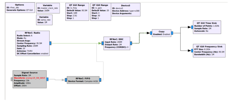
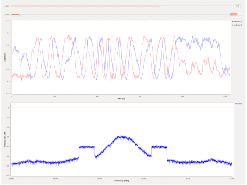
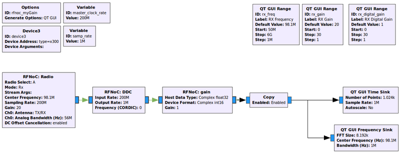
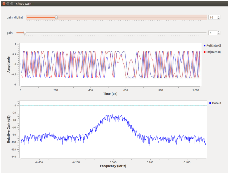
The GNU Radio flowgraph rfnoc_ddc.grc is an example that can be run using the default RFNoC image. Below are screenshots of the flowgraph and what it produces.
NOTE: Copy Block: In the RFNoC domain, streams of data can not be split as easily as they are in the GNU Radio domain. The “copy” block depicted in the screenshot above serves the function as a stream splitter. Its main purpose, when “enabled”, is to copy the samples it is getting at its input and put them into the output, but here it is also serving as a boundary between a RFNoC-domain and a GNURadio-domain. In the flowgraph above, after this boundary is passed, the data stream can easily be split into the two sinks to have them run simultaneously (standard GNU Radio functionality). It is possible to connect the GNU Radio blocks directly to RFNoC blocks without a “copy” block, but only one would work at a time (the other ones would have to be disabled). Another way to split data streams from the RFNoC-domain is to use the ”RFNoC: split stream” block, which would split the streams in the RFNoC domain, but this is not very useful here as we are, in any case, moving into the GNURadio-domain.
For more information on GNURadio development please refer to the GNURadio user's manual and API.
Starting a custom RFNoC block using RFNoC Modtool
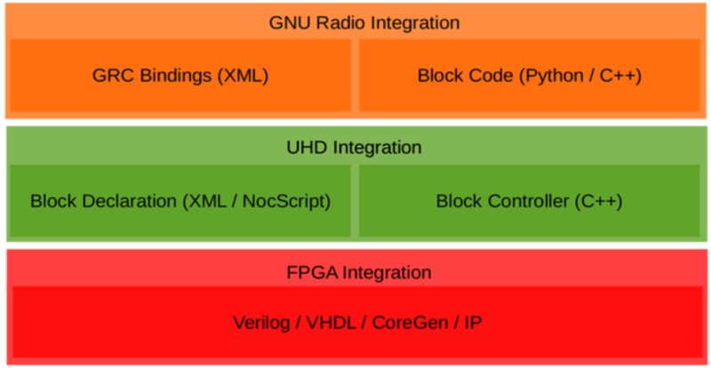
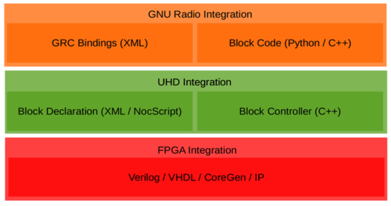
The figure below shows the basic structure of the RFNoC Stack. Corresponding code is needed in each of the three sections in order to build a custom RFNoC block with GNU Radio integration. A tool called RFNoC Modtool was created in order to minimize the effort needed to implement a new RFNoC block. RFNoC Modtool creates a custom GNU Radio OOT module with the basic structure and the necessary files for each of these sections. RFNoC Modtool is currently a part of the GNU Radio OOT module gr-ettus.
RFNoC Modtool Utilization
NOTE: Console outputs may vary depending on the version of UHD the user is running. However, functionality should be the same or similar.
Because the RFNoC Modtool has similar functionality to the gr_modtool [ gr_modtool ] provided by GNU Radio, those that have worked with gr_modtool in the past will find the RFNoC Modtool familiar.
To check the usage of the tool, run the following:
   $ rfnocmodtool help
   linux; GNU C++ version 5.4.0 20160609; Boost_105800; UHD_4.0.0.rfnoc-devel-162-g335a1317

   Usage:
   rfnocmodtool <command> [options] -- Run <command> with the given options.
   rfnocmodtool help -- Show a list of commands.
   rfnocmodtool help <command> -- Shows the help for a given command.

   List of possible commands:

   Name      Aliases          Description
   =====================================================================
   disable   dis              Disable block (comments out CMake entries for files)
   info      getinfo,inf      Return information about a given module
   remove    rm,del           Remove block (delete files and remove Makefile entries)
   makexml   mx               Make XML file for GRC block bindings
   add       insert           Add block to the out-of-tree module.
   newmod    nm,create        Create a new out-of-tree module
   rename    mv               Rename a block in the out-of-tree module.
Creating an RFNoC OOT Module
To start generating an RFNoC OOT module navigate to the source location ( i.e. cd ~/{USER_PREFIX}/src ) and type:
$ rfnocmodtool newmod [NAME OF THE MODULE]
Where [NAME OF THE MODULE] is a name the user gives the new module. In the following, a module is created with the name “tutorial”. If the user does not write the name of the module following the newmod command the tool will ask for it interactively. Running this command will create a folder containing the basic folders that you may need for a functional module.
   $ rfnocmodtool newmod tutorial
   linux; GNU C++ version 5.4.0 20160609; Boost_105800; UHD_4.0.0.rfnoc-devel-162-g335a1317

   Creating out-of-tree module in ./rfnoc-tutorial... Done.
   Use 'rfnocmodtool add' to add a new block to this currently empty module.
To see what files and directories were created run:
   $ ls rfnoc-tutorial/
   apps  cmake  CMakeLists.txt  docs  examples  grc  include  lib  MANIFEST.md  python  README.md  rfnoc  swig
In contrast with gr_modtool, this includes a folder called rfnoc, which is where the UHD/FPGA files are located.
Adding custom blocks to OOT Module
In order to add blocks to a module, navigate to the folder just created and use the add command of rfnocmodtool. Continuing with the example above, run the following:
   $ cd rfnoc-tutorial
   $ rfnocmodtool add [NAME OF THE BLOCK]
For demonstrative purposes, a block named gain will be created. The gain block will multiply samples that pass through it by a constant. As before, if the name is not given, the tool will ask the user for the name. There are several arguments that can be passed to the tool, but running the tool without any of these arguments will give the following interactive parsing output:
   $ rfnocmodtool add gain
   linux; GNU C++ version 5.4.0 20160609; Boost_105800; UHD_4.0.0.rfnoc-devel-162-g335a1317

   RFNoC module name identified: tutorial
   Block/code identifier: gain
   Enter valid argument list, including default arguments:
   Block NoC ID (Hexadecimal): 1111222233334444
   Skip Block Controllers Generation? [UHD block ctrl files] [y/N] N
   Skip Block interface files Generation? [GRC block ctrl files] [y/N] N
Hitting enter on each one of the options will take the default values.
The following is a description of the valid argument list items:
- NoC ID: This ID is a Hexadecimal number which serves as identification between the hardware part and the software part of the design. It can be as long as 16 0-9 A-F digits. If a NoC ID is not provided, it will be set to a random number.
- Block Controllers Generation: The block controllers are the C++ control that the user can apply to the UHD-part of the design. In these files, the user can add more control over this layer of the design. Depending on the complexity of the block it may be possible to add all necessary control using NoCScript (more details on NoCScript can be found in the section labeled UHD Integration). In this case the cpp/hpp block control files generation are not needed. Default is to generate as their existence will be ignored if not edited.
- Block Interface: Add more design specific functionality to the design at the GNU Radio interface by generating these block-interface files and adding necessary logic. Depending on the complexity of the block it may be possible to add all necessary control using NoC-Script. In this case the block-interface files are not needed. Default is to generate as their existence will be ignored if not edited.
NOTE: If the user does not intend to use the block controllers or is not sure if they are needed, the presence of them in the design will do no harm. It is recommended to add them. This leaves the possibility to add more functions inside them in a future stage of development.
After finishing the parsing, the following files will be generated/edited:
   Adding file 'lib/gain_impl.h'...
   Adding file 'lib/gain_impl.cc'...
   Adding file 'include/tutorial/gain.h'...
   Adding file 'include/tutorial/gain_block_ctrl.hpp'...
   Adding file 'lib/gain_block_ctrl_impl.cpp'...
   Editing swig/tutorial_swig.i...
   Adding file 'python/qa_gain.py'...
   Editing python/CMakeLists.txt...
   Adding file 'grc/tutorial_gain.xml'...
   Adding file 'rfnoc/blocks/gain.xml'...
   Adding file 'rfnoc/fpga-src/noc_block_gain.v'...
   rfnoc/testbenches/noc_block_gain_tb folder created
   Adding file 'rfnoc/testbenches/noc_block_gain_tb/noc_block_gain_tb.sv'...
   Adding file 'rfnoc/testbenches/noc_block_gain_tb/Makefile'...
   Adding file 'rfnoc/testbenches/noc_block_gain_tb/CMakeLists.txt'...
Creating FPGA portion of custom RFNoC Block
RFNoC FPGA User Interface (API)
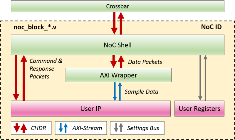
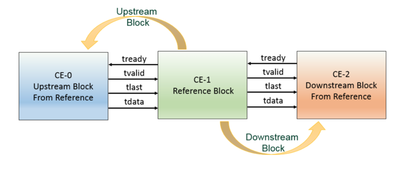
RFNoC blocks or Computation Engines (CEs) in the FPGA use a NoC Shell instance to interface with the rest of RFNoC. NoC Shell implements RFNoC's core functionality: packet muxing and demuxing, flow control, and the settings register bus (i.e. write/read control/status registers). The NoC Shell has an interface to the RFNoC AXI stream crossbar and a user interface. NoC Shell AXI stream interfaces expect CHDR packets with a proper header. See the manual for information on CHDR and SID.
NOTE: AXI Stream is an ARM AMBA standard interface. Xilinx has an AXI Reference Guide with more details on this standard.
Many designs will want to use an AXI Stream interface with only sample data. However, as stated earlier, the NoC Shell block expects CHDR packets. To ease interfacing user code, the AXI Wrapper block provides the necessary logic to strip and insert the CHDR header, effectively converting packetized sample data into streaming sample data and vice versa. The example RFNoC blocks noc_block_fft.v and noc_block_fir.v show how AXI Wrapper is used to implement existing Xilinx AXI Stream based IP within a computation engine.
NOTE: AXI Wrapper also supports AXI Stream buses for configuration. These buses are driven via the setting register bus and do not have back pressure. They also consume two user register addresses per bus.
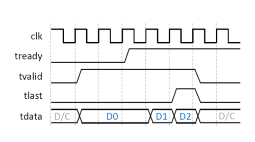
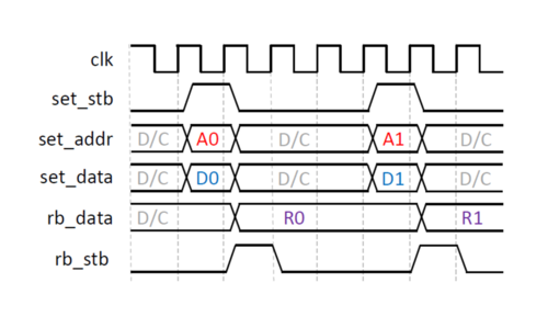
The primary user interface consists of four AXI stream interfaces ( tready, tvalid, tlast, tdata ) and a settings register bus ( 8-bit, valid user register addresses: 128-255 ).
|
AXI Stream signals:
|
|
Settings Bus signals:
|
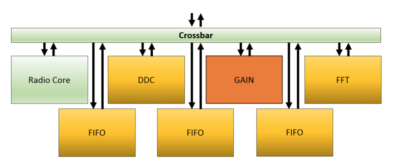
For the gain example block the following architecture is desired:
Open the file rfnoc-tutorial/rfnoc/fpga-src/noc_block_gain.v that contains the RFNoC block skeleton code that was created when the $ rfnocmodtool add gain command was run and modify the following (BOLD indicates changes to the skeleton code).
   localparam [7:0] SR_GAIN = SR_USER_REG_BASE;
   localparam [7:0] SR_TEST_REG_1 = SR_USER_REG_BASE + 8'd1;

   wire [15:0] gain;
   setting_reg #(
     .my_addr(SR_GAIN), .awidth(8), .width(16))
   sr_gain (
     .clk(ce_clk), .rst(ce_rst),
     .strobe(set_stb), .addr(set_addr), .in(set_data), .out(gain), .changed());

    always @(posedge ce_clk) begin
       case(rb_addr)
         8'd0 : rb_data <= {48'd0, gain};
         8'd1 : rb_data <= {32'd0, test_reg_1};
         default : rb_data <= 64'h0BADC0DE0BADC0DE;
       endcase
    end

    wire [31:0] pipe_in_tdata;
    wire pipe_in_tvalid, pipe_in_tlast;
    wire pipe_in_tready;

    wire [31:0] pipe_out_tdata;
    wire pipe_out_tvalid, pipe_out_tlast;
    wire pipe_out_tready;

    // Adding FIFO to ensure Pipeline
    axi_fifo_flop #(.WIDTH(32+1))
    pipeline0_axi_fifo_flop (
      .clk(ce_clk),
      .reset(ce_rst),
      .clear(clear_tx_seqnum),
      .i_tdata({m_axis_data_tlast,m_axis_data_tdata}),
      .i_tvalid(m_axis_data_tvalid),
      .i_tready(m_axis_data_tready),
      .o_tdata({pipe_in_tlast,pipe_in_tdata}),
      .o_tvalid(pipe_in_tvalid),
      .o_tready(pipe_in_tready));

    wire [15:0] i = pipe_in_tdata[31:16];
    wire [15:0] q = pipe_in_tdata[15:0];

    wire [31:0] i_mult_gain = i*gain;
    wire [31:0] q_mult_gain = q*gain;

    wire [31:0] mult_gain = {i_mult_gain[15:0], q_mult_gain[15:0]};
    axi_fifo_flop #(.WIDTH(32+1))
    pipeline1_axi_fifo_flop (
      .clk(ce_clk),
      .reset(ce_rst),
      .clear(clear_tx_seqnum),
      .i_tdata({pipe_in_tlast,mult_gain}),
      .i_tvalid(pipe_in_tvalid),
      .i_tready(pipe_in_tready),
      .o_tdata({pipe_out_tlast,pipe_out_tdata}),
      .o_tvalid(pipe_out_tvalid),
      .o_tready(pipe_out_tready));

    /* Output Signals */
    assign pipe_out_tready = s_axis_data_tready;
    assign s_axis_data_tvalid = pipe_out_tvalid;
    assign s_axis_data_tlast  = pipe_out_tlast;
    assign s_axis_data_tdata  = pipe_out_tdata;
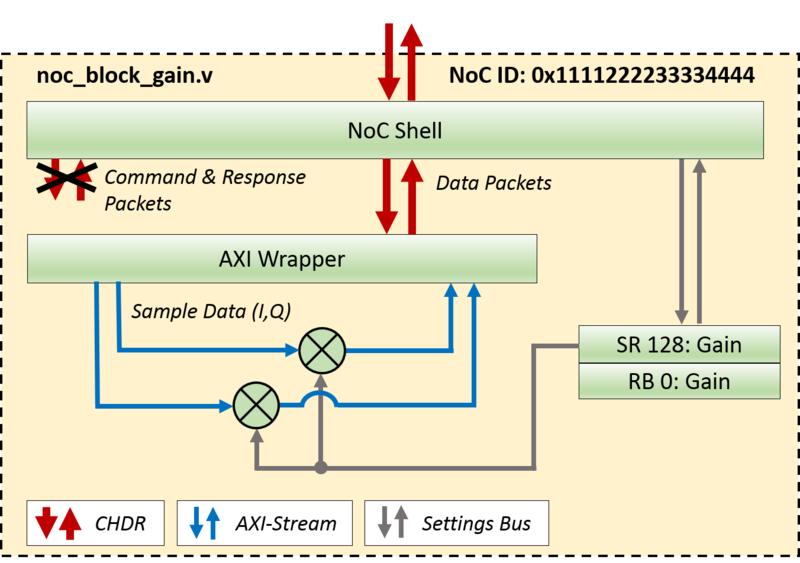
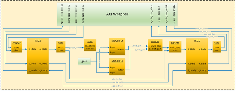
The following is a block diagram of the code created by the above Verilog:
NOTE: In order to meet timing, FIFO blocks were added to either side of the Multiplication process.
Creating and running HDL testbenches
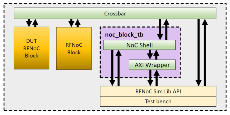
In order to make the coding iteration process more efficient, it is recommended to create testbenches for all RFNoC blocks before compiling them into the FPGA image. This allows for flaw and/or bug detection early in the design. RFNoC Modtool provides the structure and files ( e.g. noc_block_{USER_BLOCK_NAME}_tb ) for the testbenches of each of the OOT blocks that are added with the $ rfnocmodtool add command.
Below is a figure that shows the general testbench architecture that is created by the RFNoC Modtool. This architecture allows a user to test their custom block in the exact same environment it will be placed in when it is built into the RFNoC architecture. Other benefits of the testbench architecture include:
- Testing through multiple blocks (e.g. FILTER -> FFT -> AVE)
- Testing with multiple streams (e.g. RFNoC block ADD/SUB takes 2 streams, one that will have a constant added to it and one that will have a constant subtracted from it)
- Data transfer abstraction (e.g. RFNoC Sim Lib API calls to
tb_streamer.sendandtb_streamer.recvwhich take care of all the AXI stream signaling)
NOTE: The noc_block_tb block is an instantiation of the noc_block_export_io that is used in testbenches to communicate to the RFNoC architecture. This makes it possible to talk “RFNoC” to the user’s custom block and as such the custom block has a complete RFNoC experience (signaling, flowcontrol, addressing, etc)
From the Adding custom blocks to OOT Module section where the gain block was initially created, the last files generated were:
   rfnoc/testbenches/noc_block_gain_tb folder created
   Adding file 'rfnoc/testbenches/noc_block_gain_tb/noc_block_gain_tb.sv'...
   Adding file 'rfnoc/testbenches/noc_block_gain_tb/Makefile'...
   Adding file 'rfnoc/testbenches/noc_block_gain_tb/CMakeLists.txt'...
The noc_block_gain_tb is a folder generated to contain all the files related to the test bench of the gain block. Each time a new OOT block is created, a new folder will be generated as well.
Inside of this folder are the following three files:
-
CMakeLists.txt:this is an empty file used, so far, only to increase the scope of the compilers. -
noc_block_gain_tb.sv:this is a System Verilog file, in which user custom tests are to be located. This is the only file that needs to be modified. -
Makefile:This file determines the directives that run the simulation.
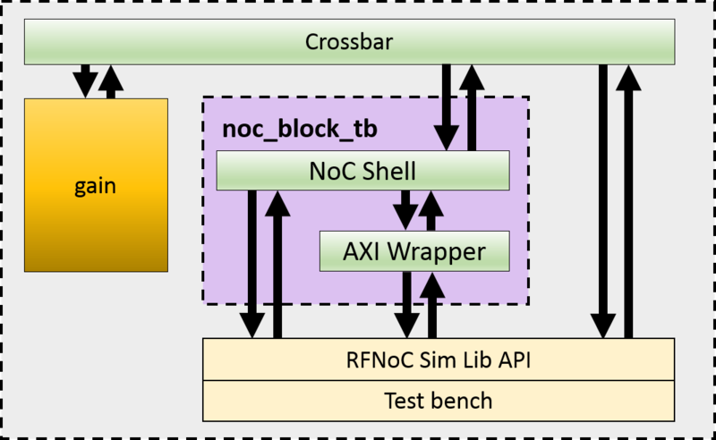
The noc_block_gain_tb.sv testbench skeleton code creates the following architecture:
Open the file rfnoc-tutorial/rfnoc/testbenches/noc_block_gain_tb/noc_block_gain_tb.sv and modify the following lines:
Right under the “Verification” section:
   initial begin : tb_main
     string s;
     logic [31:0] random_word;
     logic [63:0] readback;
     logic [15:0] gain;
In the “Test 4 -- Write / readback user registers” section:
   `TEST_CASE_START("Write / readback user registers");
   random_word = $random();
   tb_streamer.write_user_reg(sid_noc_block_gain, noc_block_gain.SR_GAIN, random_word[15:0]);
   tb_streamer.read_user_reg(sid_noc_block_gain, 0, readback);
   $sformat(s, "User register 0 incorrect readback! Expected: %0d, Actual %0d", readback[15:0], random_word[15:0]);
   `ASSERT_ERROR(readback[15:0] == random_word[15:0], s);
In the “Test 5 -- Test sequence” section:
   `TEST_CASE_START("Test sequence");
   gain = 100;
   tb_streamer.write_user_reg(sid_noc_block_gain, noc_block_gain.SR_GAIN, gain);
   fork
     begin
       cvita_payload_t send_payload;
       for (int i = 0; i < SPP/2; i++) begin
         send_payload.push_back(64'(i));
       end
       tb_streamer.send(send_payload);
     end
     begin
       cvita_payload_t recv_payload;
       cvita_metadata_t md;
       logic [63:0] expected_value;
       tb_streamer.recv(recv_payload,md);
       for (int i = 0; i < SPP/2; i++) begin
         expected_value = i*gain;
Test #4 verifies that we can write and readback the gain value. Test #5 writes to the gain register, sends a sample set in the form of a ramp (1, 2, 3, 4, etc) to the RFNoC gain block and finally reads the values from the gain block and compares them to expected values. The followings steps will allow the user to run this testbench.
From within the rfnoc-tutorial directory, create a build directory and enter it by running:
$ mkdir build && cd build/
The next step is to run cmake. If PyBOMBS was used to create the development sandbox, cmake will automatically detect the location of the fpga repository. If PyBOMBS was not used, the user must provide the location of where the fpga repository is installed.
If PyBOMBS used, run:
$ cmake ../
If PyBOMBS not used, run:
$ cmake [-DUHD_FPGA_DIR=/PATH/TO/FPGA/REPOSITORY] ../
Final output from the $ cmake ../ command:
   -- Configuring done
   -- Generating done
   -- Build files have been written to: /home/widow/rfnoc/src/rfnoc-tutorial/build
The following command will modify the necessary files and set the correct path to the simulation tools. From now on, every time a new block is added, this command will be run automatically. Remember, only run the following command once for each OOT module (not RFNoC block, but OOT module) created:
   $ make test_tb
   Scanning dependencies of target test_tb
   Built target test_tb
Testbenches can be executed by running the command:
$ make noc_block_[name_of_your_block]_tb
The gain block testbench can be run by running the following command:
$ make noc_block_gain_tb
The simulation will start. Final output should look like this:
   ========================================================
   TESTBENCH STARTED: noc_block_gain
   ========================================================
   [TEST CASE   1] (t=000000000) BEGIN: Wait for Reset...
   [TEST CASE   1] (t=000001002) DONE... Passed
   [TEST CASE   2] (t=000001002) BEGIN: Check NoC ID...
   Read GAIN NOC ID: 1111222233334444
   [TEST CASE   2] (t=000001238) DONE... Passed
   [TEST CASE   3] (t=000001238) BEGIN: Connect RFNoC blocks...
   Connecting noc_block_tb (SID: 1:0) to noc_block_gain (SID: 0:0)
   Connecting noc_block_gain (SID: 0:0) to noc_block_tb (SID: 1:0)
   [TEST CASE   3] (t=000005457) DONE... Passed
   [TEST CASE   4] (t=000005457) BEGIN: Write / readback user registers...
   [TEST CASE   4] (t=000006888) DONE... Passed
   [TEST CASE   5] (t=000006888) BEGIN: Test sequence...
   [TEST CASE   5] (t=000007633) DONE... Passed
   ========================================================
   TESTBENCH FINISHED: noc_block_gain
    - Time elapsed:   7700 ns
    - Tests Expected: 5
    - Tests Run:      5
    - Tests Passed:   5
   Result: PASSED
   ========================================================
   $finish called at time : 7700 ns : File "/home/widow/rfnoc/src/rfnoc-tutorial/rfnoc/testbenches/noc_block_gain_tb/noc_block_gain_tb.sv" Line 10
   INFO: [USF-XSim-96] XSim completed. Design snapshot 'noc_block_gain_tb_behav' loaded.
   INFO: [USF-XSim-97] XSim simulation ran for 1000000000us
   launch_simulation: Time (s): cpu = 00:00:10 ; elapsed = 00:00:12 . Memory (MB): peak = 966.387 ; gain = 54.848 ; free physical = 3080 ; free virtual = 29888
   # if [string equal $vivado_mode "batch"] {
   #     puts "BUILDER: Closing project"
   #     close_project
   # } else {
   #     puts "BUILDER: In GUI mode. Leaving project open."
   # }
   BUILDER: Closing project
   ****** Webtalk v2015.4 (64-bit)
     **** SW Build 1412921 on Wed Nov 18 09:44:32 MST 2015
     **** IP Build 1412160 on Tue Nov 17 13:47:24 MST 2015
       ** Copyright 1986-2015 Xilinx, Inc. All Rights Reserved.

   source /home/widow/rfnoc/src/rfnoc-tutorial/rfnoc/testbenches/noc_block_gain_tb/xsim_proj/xsim_proj.hw/webtalk/labtool_webtalk.tcl -notrace
   INFO: [Common 17-206] Exiting Webtalk at Tue Jan 10 23:26:20 2017...
   INFO: [Common 17-206] Exiting Vivado at Tue Jan 10 23:26:22 2017...
   Built target noc_block_gain_tb
With every custom block created, a make directive will be available to run the simulation from the build directory.
Building the FPGA image with a custom user block
In this section steps are given on how to initiate an FPGA build while incorporating the user’s custom RFNoC block. The first sections give general information on building RFNoC images. The remaining two sections show how to initiate FPGA builds using a command line interface and using a graphical interface (coming out soon), respectively.
Discussion on number of blocks in an FPGA image
There is a maximum number of blocks that can be added for each device. The maximum amount of computation engines (CEs/RFNoC blocks) that each device can use is 16, but the amount of custom blocks that can be added depends on the device.
If using a device from the X3xx series, from the 16 CEs, there are 6 that will be always added and are not subject to direct customization: 1 CE for the AXI bus, 1 CE for the Ethernet Interface, 2 Radios and 2 Dma FIFOS. Because of this, the application will only allow a number of 10 custom blocks on the X3xx series.
If using a device from the E3xx series, 2 CE engines are always added and are not subject to direct customization: 1 CE for the AXI bus and 1 Radio. This would virtually allow 14 slots for custom blocks. However, given the size of the FPGA on the E3xx series of devices, the application only allows a number of 6 custom blocks.
NOTE: Blocks with higher resource utilization may fill up the FPGA and force the user to include less blocks.
Verify the current maximum values by running the uhd_images_builder.py utility from the scripts directory.
   $ cd {USER_PREFIX}/src/uhd-fpga/usrp3/tools/scripts
   $ uhd_image_builder.py --help
Discussion on FPGA image targets
RFNoC target names follow the pattern {DEVICE}_RFNOC_{BUILD_TYPE} with the following build types:
-
HG:1GigE on SFP+ Port0, 10Gig on SFP+ Port -
XG:10GigE on both SFP+ ports -
HLS:Vivado High Level Synthesis enabled -
sgX:Speed grade for E300 devices (1 or 3)
Some examples are:
-
X310_RFNOC_HG -
X300_RFNOC_HG -
X310_RFNOC_XG -
X300_RFNOC_XG -
X310_RFNOC_HLS_HG -
X300_RFNOC_HLS_HG -
E310_RFNOC(this is for the speed grade 1 FPGA version of E310, append_sg3for speed grade 3)
NOTE: E310, E312 and E313 all have the same FPGA hardware and therefore will use the E310_RFNOC_{BUILD_TYPE} target. USRP E3xx devices have either sg1 or sg3 hardware, please visit here to find out how to differentiate.
Additional information about the build targets can be found at the build instructions for USRP3, found here.
Image building using the command line
The script uhd_image_builder.py is used to generate the NoC block instantiation file and build the FPGA image. Run the help menu by typing:
   $ cd {USER_PREFIX}/src/uhd-fpga/usrp3/tools/scripts
   $ ./uhd_image_builder.py --help

   usage: uhd_image_builder.py [-h] [-I INCLUDE_DIR [INCLUDE_DIR ...]]
                               [-m MAX_NUM_BLOCKS] [--fill-with-fifos]
                               [-o OUTFILE] [-d DEVICE] [-t TARGET] [-g] [-c]
                               [blocks [blocks ...]]

   Generate the NoC block instantiation file

   positional arguments:
     blocks                List block names to instantiate.

   optional arguments:
     -h, --help            show this help message and exit
     -I INCLUDE_DIR [INCLUDE_DIR ...], --include-dir INCLUDE_DIR [INCLUDE_DIR ...]
                           Path directory of the RFNoC Out-of-Tree module
     -m MAX_NUM_BLOCKS, --max-num-blocks MAX_NUM_BLOCKS
                           Maximum number of blocks (Max. Allowed for x310|x300:
                           10, for e300: 6)
     --fill-with-fifos     If the number of blocks provided was smaller than the
                           max number, fill the rest with FIFOs
     -o OUTFILE, --outfile OUTFILE
                           Output /path/filename - By running this directive, you
                           won't build your IP
     -d DEVICE, --device DEVICE
                           Device to be programmed [x300, x310, e310]
     -t TARGET, --target TARGET
                           Build target - image type [X3X0_RFNOC_HG,
                           X3X0_RFNOC_XG, E310_RFNOC_sg3...]
     -g, --GUI             Open Vivado GUI during the FPGA building process
     -c, --clean-all       Cleans the IP before a new build
Here are details on the usage of the script which is followed by an example:
Blocks: The first arguments are the names of RFNoC blocks that the user wants to have compiled into the new image which are separated by a space. They can be custom blocks from the user’s OOT module or from the ones that are provided from Ettus, or a combination. Blocks provided by Ettus Research are listed (among other sources necessary for the FPGA build) in the {USER_PREFIX}/src/uhd-fpga/usrp3/lib/rfnoc/Makefile.srcs file.
These blocks can be identified by the following pattern:
noc_block_{NAME}.v
However, as all the RFNoC blocks have the same noc_block_ prefix, for simplicity this prefix is omitted when listing the blocks in the uhd_image_builder.py utility. As an example of the incorrect and correct way of adding blocks, consider the following examples when adding the noc_block_null_source_sink and noc_block_siggen blocks:
Incorrect method:
$ ./uhd_image_builder.py noc_block_null_source_sink noc_block_siggen ...
Correct method:
$ ./uhd_image_builder.py null_source_sink siggen ...
NOTE: Blocks generated by the RFNoC Modtool follow the same naming convention.
There is an increasing list of pre-built blocks. Here is a sample:
-
axi_fifo_loopback -
axi_dma_fifo -
fir_filter -
fft -
null_source_sink -
schmidl_cox -
packet_resizer -
split_stream -
vector_iir -
addsub -
window -
keep_one_in_n -
pfb -
export_io -
conv_encoder_qpsk -
siggen -
logpwr -
fosphor -
moving_avg -
ddc -
duc
RFNoC related blocks generally reside in fpga/usrp3/lib/rfnoc/.
| Block | Filename | Description |
|---|---|---|
| FIFO | noc_block_axi_fifo_loopback.v | Simple FIFO loopback / passthrough block. |
| FFT | noc_block_fft.v | Xilinx coregen based Fast Fourier Transform up to length 4096. |
| FIR | noc_block_fir_filter.v | Xilinx coregen based Finite Impulse Response Filter, 41 taps, reconfigurable tap coefficients. |
| Window | noc_block_window.v | Windowing block for use with FFT block. |
| Vector IIR | noc_block_vector_iir.v | Single pole IIR with configurable coefficients that filters data along vectors (i.e. parallel streams of samples). Useful with FFT output. |
| Keep One in N | noc_block_keep_one_in_n.v | Keeps one packet every N packets. |
| AddSub | noc_block_addsub.v | Example of using multiple block ports in a single RFNoC block to add and subtract streams. |
| Null Source Sink | noc_block_null_source_sink.v | Generates dummy packets and can consume packets at a configurable rate. Useful for testing. |
| Packet Resizer | noc_block_packet_resizer.v | Resizes input packets to a configurable size (larger or smaller than source packets). |
| Split Stream | noc_block_split_stream.v | Replicates an input stream to a configurable number of output streams. |
NOTE: There is a restriction on the amount of blocks that can added into the FPGA image, see the section in this Application Note labeled Discussion on number of blocks in an FPGA image for more information.
-I INCLUDE_DIR: The -I directive provides the path to top OOT directory, which contains the users rfnoc/fpga-src directory which contains the custom blocks. This path is needed by the Xilinx Vivado tool. Inside the fpga-src directory there is a file called Makefile.srcs that contains the path of the OOT module and a list of all the custom OOT blocks. This is an auto generated file, which is amended every time a new block is added to the OOT module. Manually modifying this file is not recommended. If there are multiple OOT modules with various custom blocks that reside in different directories the way to include them all is by separating the different paths by a space (e.g. -I /first/OOT/path/ /second/OOT/path/).
IMPORTANT: Please be sure to terminate the path of your OOT with the "/" character. Otherwise the path might not be recognized.
-d DEVICE: The -d directive directs the script on which USRP device the build is for. If no –d is included the default is –d x310. Generation-3 USRPs and above all support RFNoC.
-t TARGET: The –t directive directs the script on which type of image to build for the chosen device. With each USRP device there are several build options to choose from. Detailed information about the build targets can be found at the build instructions for USRP3, found here. If -t is not included, a default target will be chosen for the given device. For example, the default X310_RFNOC_HG target builds for the –d x310 device. More details on targets can be found in the section of this Application Note labeled Discussion on FPGA image targets.
-m MAX_NUM_BLOCKS: The –m directive specifies the max number of RFNoC blocks to build on the FPGA image. An RFNoC image does not need to fill all available slots with RFNoC blocks.
--fill-with-fifos: The --fill-with-fifos directive will fill the empty RFNoC block slots with FIFOS. As an example, if a user indicates three RFNoC blocks by name and also specifies –m 5 then the other two slots will be filed with FIFOs.
-o OUTFILE: With the -o directive, the RFNoC blocks instantiation file is generated and saved at the desired path with the given name for the user to inspect. The FPGA image will NOT build if this directive is provided. The purpose of the uhd_image_builder.py script is to auto generate an instantiation file and populate the source files needed for the Xilinx Vivado tool to build the FPGA image, however, it may be desirable to only see the effect of adding a custom OOT module in the fpga/ directory, or for inspecting the instantiation file. When the directive is not provided the rfnoc_ce_auto_inst_x3x0.v file is overwritten and the FPGA image build process will start automatically (standard use).
-g, --GUI: Open Vivado GUI during the FPGA building process
-c, --clean-all: Cleans the IP before a new build
Here is how to create an X310 FPGA image incorporating the gain block that was created earlier in this Application Note:
   $ cd {USER_PREFIX}/src/uhd-fpga/usrp3/tools/scripts
   $ ./uhd_image_builder.py gain ddc fft -I {USER_PREFIX}/src/rfnoc-tutorial/ -d x310 -t X310_RFNOC_HG -m 6 --fill-with-fifos
At the end of a successful compilation process, write the new image to a USRP. The following command will load the new image. Update the {IP_Address} of the USRP and {USER_PREFIX} to the appropriate values for your configuration before running the command.
$ uhd_image_loader --args "type=x300,addr={IP_ADDRESS}" --fpga-path {USER_PREFIX}/src/uhd-fpga/usrp3/top/x300/build/usrp_x310_fpga_RFNOC_HG.bit
NOTE:
- The FPGA image building process may take over an hour.
- FPGA images are specific to the USRP device NOT the USRP series. For example, a USRP X300 FPGA image will NOT work on a USRP X310 and vice versa. Loading an image that does not correspond to a USRP device will likely brick the device. Additional instructions on flashing a custom image to a device can be found here for X3xx series and here for E3xx series.
- [Environment setup] - The
uhd_image_builder.pyscript will also set up the Xilinx Vivado environment by automatically running thesetupenv.shscript located in the{USER_PREFIX}/src/uhd-fpga/usrp3/top/{device}directory. Thesetupenv.shscript assumes that Xilinx Vivado is installed in the default location of/opt/Xilinx/Vivado. If the installation is in a different directory thesetupenv_base.shscript will need to be modified. The script is located at:{USER_PREFIX}/src/uhd-fpga/usrp3/tools/scripts/setupenv_base.sh
Besides the custom gain block, a DDC and FFT block are also being added along with three FIFOs. The DDC, FFT and FIFO blocks are already in the script's path and therefore do not need their path specified (they ship with the Ettus Research FPGA code). The reason three FIFOs are added is because the max number of blocks was specified to be 6 ( -m 6 ) and since only 3 blocks were specifically named the other three slots are filled with FIFOs.
NOTE: Instructions on flashing the image to a device can be found here for X3xx series and here for E3xx series. FPGA images are specific to the USRP device NOT the USRP series. For example, a USRP X300 FPGA image will NOT work on a USRP X310 and vice versa. Loading an image that does not correspond to a USRP device will likely brick the device.
Once the newly compiled image is loaded onto a USRP X3xx running the following command will show what RFNoC blocks are available on the FPGA:
   $ uhd_usrp_probe


   |   |     _____________________________________________________
   |   |    /
   |   |   |       RFNoC blocks on this device:
   |   |   |
   |   |   |   * DmaFIFO_0
   |   |   |   * Radio_0
   |   |   |   * Radio_1
   |   |   |   * Block_0
   |   |   |   * DDC_0
   |   |   |   * FFT_0
   |   |   |   * FIFO_0
   |   |   |   * FIFO_1
   |   |   |   * FIFO_2
NOTE: The reason the custom block is called Block_0 and not gain_0 is because there is still host side software/files that need updated in order for this block to populate it’s proper name. A following section (UHD Integration) will step through the process of updating those host side files.
Using a graphical interface
A graphical user interface for FPGA generation and building is shipped along with the uhd_image_builder.py script. This intuitive application aids in setting up a custom FPGA build.
This utility is located in the same scripts directory as uhd_image_builder.py.
To run it, enter the following commands:
   $ cd {USER_PREFIX}/src/uhd-fpga/usrp3/tools/scripts/
   $ ./uhd_image_builder_gui
The application will then be launched:
1. Select build target: In this panel the available build targets are listed. This list may vary depending on which branch of the FPGA repository this user is using. Only RFNoC targets are listed. The build type descriptions are:
-
HG:1GigE on SFP+ Port0, 10Gig on SFP+ Port1 -
XG:10GigE on both SFP+ ports -
HLS:Vivado High Level Synthesis enabled -
sgX:Speed grade for E300 devices (1 or 3)
2. List of blocks available: In this panel the available blocks are listed that can be included into a custom design. This list separates the RFNoC blocks provided by Ettus Research and the OOT modules and corresponding blocks that the user adds. Given the hardware differences between the X3xx and E3xx devices, this list will dynamically change when a different device is selected from the panel on the left. This implies that it is necessary to add the OOT modules for each device independently. This is accomplished by using the Add OOT Blocks feature of the application, details of which are explained at #7 (Add OOT Blocks).
3. Blocks in current design: This section gives information on the MAX number of blocks for a given USRP (based on the target selection). There is a maximum number of blocks that can be added for each device. See the section in this App Note labeled "Discussion on number of blocks in an FPGA image" for more information.
4. Blocks in current design: This panel will be populated by adding elements from the available blocks. All the blocks listed in here will be compiled into the FPGA custom image. There is a maximum number of blocks that can be added for each device. See the section in this App Note labeled "Discussion on number of blocks in an FPGA image" for more information.
5. Add button (>>): Manually add the blocks from the central panel into your design.
6. Remove button (<<): Remove blocks from the current design (far-left panel)
7. Fill with FIFOs: By checking this box, the design will fill any available/unspecified block slots with FIFOs. The number of FIFO blocks that will be instantiated is based on the rules of amount of blocks explained at #3. When less than the max amount of blocks are needed for certain implementation, many users choose to fill their design with FIFO blocks.
8. Open Vivado GUI: Open Vivado GUI during the FPGA building process. This allows the user to save a Vivado project with all IP and work within the Vivado GUI for development.
9. Clean IP: Cleans the IP before a new build (recompiles all IP).
10. Add OOT blocks: Manually add RFNoC Modtool-generated OOT modules by pointing the application to the Makefile.srcs file, which is located in the {USER_PREFIX}/src/{USER-OOT-moddir}/rfnoc/fpga-srcs/ directory. After adding this file, blocks will appear under “OOT blocks for XXXX devices”
11. Show Instantiation File: The application auto-generates the instantiation file that is going to be used by Vivado to build the FPGA image. This instantiation file can be viewed and edited before starting the build by clicking this button.
12. Import from GRC: If the user has a GNU Radio flowgraph with RFNoC blocks already in it, this application can read what RFNoC blocks are in the flowgraph and populate the Blocks in current design section of the application with the necessary RFNoC blocks. NOTE: All RFNoC blocks pulled from a .grc file must be in the of List of blocks available before beginning the build.
13. Generate .bit file: Start the build by clicking this button.
14. uhd_image_builder command: The command line command with arguments is dynamically build here as the user selects different options. The user could save this command to use next time they build/compile an FPGA image to avoid having to select all options again.
NOTE: See the latter end of the previous section for additional information on what to expect once the compile has started as well as final output.
Creating Software/Host portion of custom RFNoC Block
Now that the FPGA portion is complete the next step is to add software integration to UHD and GNU Radio as depicted in the RFNoC Stack below.
UHD integration
Despite the data processing happening on the FPGA, the host software still has a lot of responsibilities in order for an RFNoC application to function. For example, it needs to know which settings registers are available within an RFNoC block, or what kind of input and output a block has. All of this information goes into the Block Declaration, which is an XML file that is readable by UHD. Often, some simple logic needs to be embedded in the XML file, which we can do by using a simple scripting language called Noc-Script. Changes to the block declaration file are immediately imported into UHD every time an application is executed, and therefore, no software development toolchain needs to be set up.
The list of things declared by the block declaration file includes:
- Block name and Noc-ID
- Registers
- Inputs and outputs (including types)
In some cases, additional C++ code is required to properly control a block from software. In this case, a Block Controller file is required as well as the declaration file. In most cases, the default block controller provided by UHD is sufficient, so no C++ code needs to be written. Writing custom block controllers requires more effort, and means having to set up a programming toolchain. A common reason to write custom C++ block controllers is if setting a register requires a lot of computation, which is not feasible to do within a block declaration file (e.g., using Noc-Script).
Skeleton code for both the block declaration and the block controller (if required) can be generated through RFNoC Modtool.
Because the gain block does not require anything other than simply reading and writing to a single register the default block controller will suffice for this example. However, we will need to add information about the register.
Open the gain.xml file located in the /rfnoc-tutorial/rfnoc/blocks directory and add the following:
   <?xml version="1.0"?>
   <!--Default XML file-->
   <nocblock>
     <name>gain</name>
     <blockname>gain</blockname>
     <ids>
       <id revision="0">1111222233334444</id>
     </ids>
     <!-- Registers -->
     <registers>
       <setreg>
         <name>GAIN</name>
         <address>128</address>
       </setreg>
     </registers>
     <!-- Args -->
     <args>
       <arg>
         <name>gain</name>
         <type>double</type>
         <value>1.0</value>
         <check>GE($gain, 0.0) AND LE($gain, 32767.0)</check>
         <check_message>Invalid gain.</check_message>
         <action>
           SR_WRITE("GAIN", IROUND($gain))
         </action>
       </arg>
     </args>
     <!--One input, one output. If this is used, better have all the info the C++ file.-->
     <ports>
       <sink>
         <name>in0</name>
         <type>sc16</type>
       </sink>
       <source>
         <name>out0</name>
         <type>sc16</type>
       </source>
     </ports>
   </nocblock>
GNU Radio Integration
GNU Radio is built around the concept of blocks, similarly to RFNoC. When mapping RFNoC into an application, the simple constraint is made that every RFNoC block maps to a single GNU Radio block. Thus, when creating mixed GNU Radio/RFNoC applications, there is a very clear 1:1 mapping between what’s happening in RFNoC and GNU Radio.
Since most RFNoC blocks behave very similar to one another from GNU Radio’s perspective, it is generally not required to write C++ code for another block. Rather, a default block provided by RFNoC can be used with appropriate configuration. However, in some cases it may be desirable or even necessary to write a custom GNU Radio block for more specific controlling of the underlying RFNoC block. GNU Radio allows writing blocks in either C++ or Python, but since UHD and RFNoC do not have a Python API, a custom wrapper for an RFNoC block needs to be written in C++. RFNoC Modtool will create skeleton files for this purpose.
The most popular and effective way to use GNU Radio is through the graphical interface, the GNU Radio Companion (GRC). GRC requires a separate description of every GNU Radio block in order to become available in the graphical UI, and the same is true for an RFNoC block that is wrapped in a GNU Radio block (even if the generic RFNoC block wrapper is used). For GNU Radio 3.7 and earlier, GRC bindings for blocks are written as XML files with interspersed Cheetah or Python statements. For a more detailed tutorial on how to write these files, refer to the GNU Radio Documentation and associated tutorials.
GNU Radio Block Code
- C++ or Python, although RFNoC blocks need to be written in C++ (if at all)
- How does GNU Radio interface to RFNoC?
- via C++ infrastructure code in
gr-ettus -
gr-ettusprovides a base RFNoC block class - Users extend base class for their RFNoC blocks
- Many blocks can use base class “as is”
- No C++ or Python code!
- via C++ infrastructure code in
-
rfnoc-tutorial/lib/gain_impl.cc- The gain block does not need anything additional
GNU Radio Companion Bindings
- XML
- Describes GNU Radio blocks to GRC
- No recompilation
- Requirement of GNU Radio Companion
- Not strictly necessary for GNU Radio
- Tutorial on how to write them:
- Skeleton file generated by RFNoC Modtool
Open the tutorial-gain.xml file located in the rfnoc-tutorial/grc directory and edit as follows:
   <?xml version="1.0"?>
   <block>
     <name>RFNoC: gain</name>
     <key>tutorial_gain</key>
     <category>tutorial</category>
     <import>import tutorial</import>
     <make>tutorial.gain(
       self.device3,
       uhd.stream_args( \# TX Stream Args
           cpu_format="fc32",
           otw_format="sc16",
           args="gr_vlen={0},{1}".format(${grvlen}, "" if $grvlen == 1 else "spp={0}".format($grvlen)),
       ),
       uhd.stream_args( \# RX Stream Args
           cpu_format="fc32",
           otw_format="sc16",
           args="gr_vlen={0},{1}".format(${grvlen}, "" if $grvlen == 1 else "spp={0}".format($grvlen)),
       ),
       $block_index, $device_index,
     )
   self.$(id).set_arg("gain", $gain)
     </make>
     <callback>set_arg("gain", $gain)</callback>
     <!-- Make one 'param' node for every Parameter you want settable from the GUI.
           Sub-nodes:
           * name
           * key (makes the value accessible as $keyname, e.g. in the make node)
           * type -->

        .
        .
        .

       <option>
         <name>Byte</name>
         <key>u8</key>
       </option>
     </param>
     <param>
       <name>Gain</name>
       <key>gain</key>
       <value>1.0</value>
       <type>real</type>
     </param>

     <!-- Make one 'sink' node per input. Sub-nodes:
           * name (an identifier for the GUI)
           * type
           * vlen
           * optional (set to 1 for optional inputs) -->
     <sink>
       <name>in</name>
       <type>complex</type>
       <vlen>$grvlen</vlen>
       <domain>rfnoc</domain>
     </sink>

     <!-- Make one 'source' node per output. Sub-nodes:
           * name (an identifier for the GUI)
           * type
           * vlen
           * optional (set to 1 for optional inputs) -->
     <source>
       <name>out</name>
       <type>complex</type>
       <vlen>$grvlen</vlen>
       <domain>rfnoc</domain>
     </source>
   </block>
NOTE: Indentation spacing is important in the <make> section.
Compile, Install and Verify
   $ cd {USER_PREFIX}/src/rfnoc-tutorial/build
   $ make install

   $ uhd_usrp_probe

   |   |     _____________________________________________________
   |   |    /
   |   |   |       RFNoC blocks on this device:
   |   |   |
   |   |   |   * DmaFIFO_0
   |   |   |   * Radio_0
   |   |   |   * Radio_1
   |   |   |   * gain_0
   |   |   |   * DDC_0
   |   |   |   * FFT_0
   |   |   |   * FIFO_0
   |   |   |   * FIFO_1
   |   |   |   * FIFO_2
NOTE: In the case where the gain_0 does not appear but Block_0 does: Most likely, the XML block declaration file (see UHD Integration section) for the block contains a NoC-ID that does not match with any NoC-ID defined in the hardware part of the design. The user has to be certain that the description files are up-to-date and that the NoC-ID matches in the SW and HW side. See the UHD Integration section to update those host side files.
Testing out the custom block
At this point the custom gain RFNoc Block (Computation Engine) can be used within a GNU Radio flowgraph. Below is an example GRC flowgraph using our new block as well as the output application it produces.
NOTE: Copy Block: In the RFNoC domain, streams of data can not be split as easily as they are in the GNU Radio domain. The “copy” block depicted in the screenshot above serves the function as a stream splitter . It’s main purpose, when “enabled”, is to copy the samples it is getting at its input and putting then into the output, but here it is also serving as a boundary between a RFNoC-domain and a GNURadio-domain. In the flowgraph above. after this boundary is passed, the data stream can easily be split into the two sinks to have them run simultaneously (standard GNU Radio functionality). It is possible to connect the GNU Radio blocks directly to RFNoC blocks without a “copy” block, but only one would work at a time (the other ones would have to be disabled). Another way to split data streams from the RFNoC-domain is to use the ”RFNoC: split stream” block, which would split the streams in the RFNoC domain, but this is not very useful here as we are, in any case, moving into the GNURadio-domain.
Troubleshooting
Xilinx Vivado
Compile issues
Synthesis is failing
Verify all the correct Xilinx prerequisite software is installed.
Additional helpful information can be found in the following Xilinx forum posts:
- https://forums.xilinx.com/t5/Synthesis/Synthesis-failed-without-reporting-any-error/td-p/686000
- https://forums.xilinx.com/t5/Installation-and-Licensing/Vivado-on-Linux-synthesis-fails-with-no-error-message/td-p/732143
Environment Setup
The uhd_image_builder.py script will also set up the Xilinx Vivado environment by automatically running the setupenv.sh located in the {USER_PREFIX}/src/uhd-fpga/usrp3/top/{device} directory. The setupenv.sh script assumes that Xilinx Vivado is installed in the default location of /opt/Xilinx/Vivado. If the installation is in a different directory, then the setupenv_base.sh script will need to be modified. The script is located at: {USER_PREFIX}/src/uhd-fpga/usrp3_rfnoc/tools/scripts/setupenv_base.sh.
Reference Files
The following reference files are included within the gain_src.tar.gz archive linked below:
- gain.xml
- noc_block_gain.v
- noc_block_gain_tb.sv
- tutorial_gain.xml
- rfnoc_gain.grc
Links and Additional Resources
RFNoC additional resources
- Video: RFNoC Getting Started Video Tutorial
- USRP Mailing List
- RFNoC Software Resources Page
- RFNoC Introduction
- RFNoC Deep Dive: FPGA
- RFNoC Deep Dive: Host side
- Video: RFNoC presented at Wireless @ Virginia Tech, 2015
- Explaining the slides of Intro, FPGA and Host presentations above (in that order).
- Video: It's the RFNoC Life for Us by Martin Braun at GRCon16, 2016

