Difference between revisions of "Synchronization and MIMO Capability with USRP Devices"
(→Introduction) |
|||
| Line 1: | Line 1: | ||
Discusses the requirements for Multiple-In-Multiple-Out (MIMO) and phased-array systems. Summarizes the MIMO capability of each USRP device and daughterboard, and shows how to build MIMO systems with the USRP product family. | Discusses the requirements for Multiple-In-Multiple-Out (MIMO) and phased-array systems. Summarizes the MIMO capability of each USRP device and daughterboard, and shows how to build MIMO systems with the USRP product family. | ||
| − | + | Application Note Number: AN-5501 | |
| + | Authors: John Smith and Jane Smith | ||
| + | |||
| + | Last Modified Date: 2016/04/15 | ||
| + | |||
| + | https://www.ettus.com/content/files/kb/mimo_and_sync_with_usrp_updated.pdf | ||
==Introduction== | ==Introduction== | ||
Revision as of 16:14, 15 April 2016
Discusses the requirements for Multiple-In-Multiple-Out (MIMO) and phased-array systems. Summarizes the MIMO capability of each USRP device and daughterboard, and shows how to build MIMO systems with the USRP product family.
Application Note Number: AN-5501
Authors: John Smith and Jane Smith
Last Modified Date: 2016/04/15
https://www.ettus.com/content/files/kb/mimo_and_sync_with_usrp_updated.pdf
Contents
- 1 Introduction
- 2 MIMO System Requirements – Time and Frequency Synchronization
- 3 Beamforming and Direction Finding Requirements
- 4 Other Variables That Effect Phase Alignment
- 5 USRP B100 and E100 – Not Recommended for MIMO
- 6 Synchronization with GPS Disciplined Oscillator
- 7 MIMO Capability of Ettus Research USRP Devices
- 8 USRP N200/N210 – Plug and Play 2x2 MIMO System
- 9 Application Example – Visual Phase Alignment with N210 2X2 MIMO System
- 10 Synchronization with 10 MHz and 1 PPS Signals
- 11 Synchronization Signals – Input Levels
- 12 Additional Resources
Introduction
Some applications require synchronization across multiple USRPTM (Universal Software Radio Peripheral) devices. Ettus ResearchTM provides several convenient solutions for synchronization. For example, two USRP N210s can be synchronized using a MIMO cable. It is also possible to synchronize more than two units using the Ettus Research OctoClock. Optional GPS-disciplined oscillators provide the capability to synchronize devices to the GPS standard over a large geographic area. This document will introduce and explain the synchronization features of the USRPTM product family and how to meet the requirements of multi-channel applications.
MIMO System Requirements – Time and Frequency Synchronization
For a transceiver to be considered MIMO-capable, each channel in the system must meet two basic requirements:
- The sample clocks must be synchronized and aligned.
- DSP operations must be performed on samples aligned in time – from the same sample clock edge.
The Ettus Research USRP N200/N210 is recommended for MIMO applications. Two USRP N200/N210s can be synchronized with the USRP MIMO cable. It is also possible to build larger MIMO systems (up to 16x16) by distributing an external reference.
Beamforming and Direction Finding Requirements
Some applications, such as beamforming and direction finding, place additional requirements on the system. In addition to sample time and sample clock alignment, the system must maintain a known phase relationship between each RF input or output. Due to phase ambiguities caused by phased- locked loops which are used for up and down-conversion, some calibration may be required to determine this phase relationship.
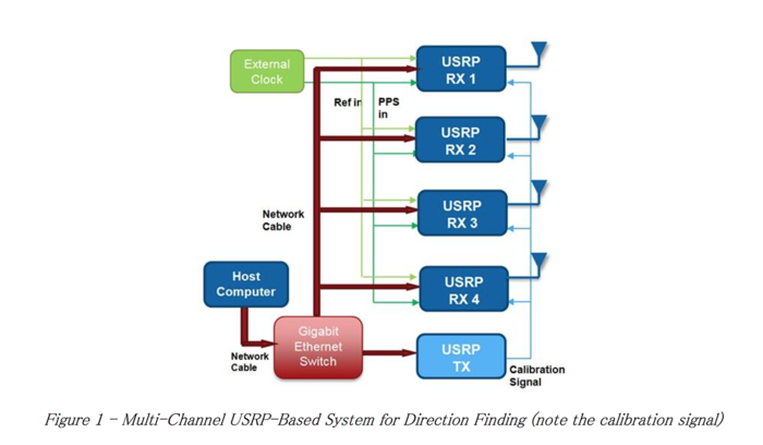
It is possible to calibrate a multi-channel system by producing a tone that is distributed to the inputs of each USRP device with match-length RF cables. An illustration of a system that uses this methodology is shown in Figure 1. User-developed software running on the host PC is used to measure the phase and amplitude differences of each channel and apply a correction.
Other Variables That Effect Phase Alignment
As mentioned, other components aside from local oscillators contribute to phase error. Filters, mixers, amplifiers and other components produce phase offsets that vary with time, temperature, mechanical conditions, etc. These types of errors can generally be calibrated out with intermittent, low-rate routines that detect the channel-to-channel phase with a calibration tone. These errors will not change with each PLL retune but may change with time and temperature variation. Thus, applications that require RF phase alignment may require periodic calibration.
USRP B100 and E100 – Not Recommended for MIMO
Like the USRP N200/N210, the USRP B100 and E100/110 can be synchronized with an external reference and PPS source. However, this does not imply the USRP B100 and E100/E110 are MIMO capable. The flexible frequency clocking architecture used in these devices produces phase ambiguity in ADC/DAC sample clocks. Therefore, sample edges will not be aligned.
Despite the sample edge misalignment, it is still possible to produce samples with relatively accurate time stamps. This is useful for time-difference-of-arrival or similar algorithms.
One exception to these statements is when you make use of a daughterboard containing more than one channel in a single slot. For example, LFRX/TX, BasicRX/TX, and TVRX2 can all be used to achieve MIMO capability with a USRP B100 or E100/110.
Synchronization with GPS Disciplined Oscillator
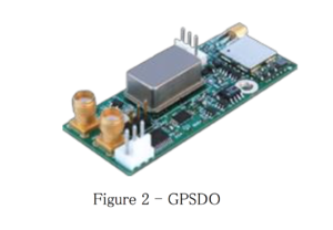
It is possible to provide time-synchronization over a wider geographic area with a GPS disciplined oscillator (GPSDO). A GPSDO derives 10 MHz/PPS signals from the GPS system. The GPSDO is accurate to approximately +/-50 ns across the globe. Ettus Research provides an optional GPSDO module with the USRP N200/N210. There is also an upgraded version of the OctoClock, which includes an internal GPSDO.
MIMO Capability of Ettus Research USRP Devices
Table 1 provides an overview of the synchronization and MIMO capabilities of the USRP product line.
| USRP Model | BW Capability (MSPS w/ 16-bit) | System Clock Input | MIMO Capable | Ext Ref. Input | 1 PPS Input | Internal GPS Disiplined Oscillator (Optional) | Plug and Play MIMO |
|---|---|---|---|---|---|---|---|
| USRP1 | 8 | X | X | ||||
| N200 | 25 | X | X | X | X | X | |
| N210 | 25 | X | X | X | X | X | |
| E100 | 4 | X | X | X | |||
| E110 | 4 | X | X | X | |||
| B100 | 8 | X | X |
The RF daughterboard selection also impacts the synchronization experience. Most daughterboards use a fractional-N synthesizer to generate the local-oscillator signals. Generally, these fractional- N synthesizers introduce a random phase offset after each retune. If phase alignment between all RF channels is required, this random phase offset will need to be measured and compensated for in software. The SBX PLL includes a resync feature that resets to a fixed phase after each retune. Thus, it may not need to be calibrated after each retune, but may require periodic calibration. This makes the SBX daughterboard the most ideal option for phased-array applications that fall within its frequency range. Also, the BasicRX/TX and LFRX/TX boards do not contain local oscillators that introduce phase errors.
| MIMO Capable | Phase Sync Feature? | |
|---|---|---|
| CBX | Yes | No |
| SBX | Yes | Yes |
| WBX | Yes | Yes, +/- 180 deg |
| XCVR2450 | Yes | No |
| DBSRX2 | Yes | No |
| TVRX2 | Yes | No |
| BasicRX/BasicTX | Yes | No |
| LFRX/LFTX | Yes | No |
USRP N200/N210 – Plug and Play 2x2 MIMO System
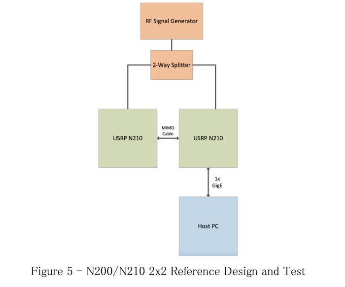
The easiest method to implement a high-performance 2x2 MIMO system is to utilize two N200/N210s synchronized with an Ettus Research MIMO cable. In this configuration, a single Gigabit Ethernet(GigE) interface can be used to communicate with both USRP devices. The USRP connected to the GigE acts as a switch and routes data to/from both USRP devices. It will also handle time synchronization of the data so the sample alignment process is transparent to the user. The total sample rate for USRP devices connected to a single GigE port on the host computer cannot exceed 25 MS/s in 16-bit mode, or 50 MS/s in 8-bit mode.
Application Example – Visual Phase Alignment with N210 2X2 MIMO System
The UHDTM API allows you to select synchronization settings for each USRP device. These settings are also exposed through GNU Radio blocks. This allows for a quick, illustrative example of how to use the N200/N210 to build a MIMO system. GNU Radio Compnion (GRC) is used for this basic illustration.
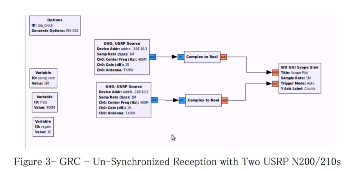
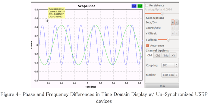
Figure 3 shows a flowgraph that receives two streams from two unsynchronized USRP devices. A 400.01 MHz tone is injected into both USRP devices, which are tuned to 400.00 MHz. The flow graph separates the real component of each complex baseband signal and plots them together on a WX GUI Scope. When the two USRP devices are synchronized, the scope sill show two, 10 kHz tones with constant relative phase. In this test case, the USRP devices are unsynchronized. Notice in Figure 4 that there are obvious phase and frequency differences between the two signals. This is a result of variations in the two unsynchronized reference clocks. Heat is applied to one of the USRP device’s internal reference crystals to amplify the frequency variation between the two units.
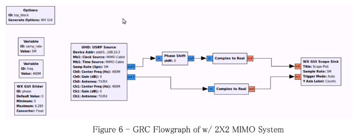
Next, plug-and-play 2X2 system is illustrated in Figure 5. Notice the relative simplicity of the system. A MIMO system is created by connecting two N200/N210s with a MIMO cable, which shares Ethernet connectivity and common 10 MHz/PPS signals. Like the unsynchronized setup that produce the scope view in Figure 4, a signal generator drives the receiver inputs of both inputs. A block diagram of the synchronized system is shown in Figure 5. The flowgraph is shown in Figure 6.
A single UHD block is used in the GRC flowgraph. The block parameters are configured to set up a 2x2 MIMO system. The settings of interest are:
   Device addr: addr0=192.168.10.2,addr1=192.168.10.3 Sync = don't sync
   Num Mboards = 2
   Mb0 Clk Src = Default
   Mb0 Time Src = Default
   ...
   Mb1 Clk Src = MIMO Cable Mb1 Time Src = MIMO Cable
These settings configure the first USRP device, Mb0, which corresponds to the first entry in the address string, to use its default reference for clocking and timing. The second USRP(Mb1) is configured to accept its frequency and timing reference from the MIMO cable. The signals are provided by Mb0. All other standard settings such as center frequency and gain assignments apply as well.
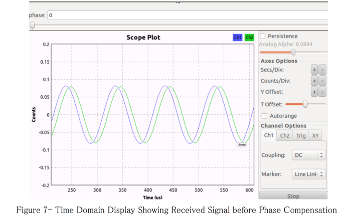
Like the first flowgraph shown, the real part of each USRP stream is displayed on a scope. A phase correction block is included to compensate for the random, but constant, phase offset discussed earlier in this paper. Figure 7 includes a screenshot of the resultant display both before phase adjustment. Note the phase is constant and the tones are the same frequency.
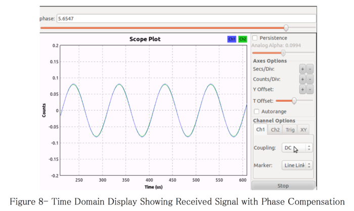
Figure 8 shows the signals with phase correction applied. In this plot, it is clear the MIMO connection has enabled the frequency and time references to be synchronized. The random phase offset is corrected with a complex phase shift in the flowgraph. In real applications, this phase correction would be implicitly generated with algorithms such as maximum-ratio combining (MRC), or periodic calibration.
This is a simple illustration of the MIMO capability provided by the USRP N200/N210. In most applications the phase compensation is implemented with some automated process. However, calibrating the devices with this type of manual correction is certainly an option.
All principles illustrated in this example are applicable to operations in the transmit direction.
Synchronization with 10 MHz and 1 PPS Signals
While the USRP N200 and N210 provide plug-and-play MIMO capability with the Ettus Research MIMO cable, it is also possible to synchronize multiple devices using external 10 MHz and 1 PPS distribution. This is useful if the developer would like to use a high-accuracy external reference such as a Rubidium source. It is also helpful if the developer must build a MIMO system with more than two channels.
If common PPS and 10 MHz signals are distributed to USRP N-Series devices, it is theoretically possible to build arbitrarily large MIMO systems. In practice, developers have built systems with up to 16 synchronized USRP devices.
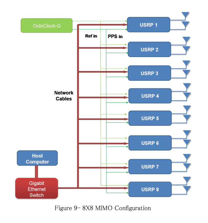
The Ettus Research OctoClock and OctoClock-G make it easy to distribute 10 MHz and 1 PPS signals for multi-channel operation. The OctoClock serves as an 8-way PPS and 10 MHz reference splitter. The user must provide a single 10 MHz and 1 PPS signal. The upgraded OctoClock-G includes a high-accuracy, internal GPS-disciplined oscillator and does not require external signals to be supplied. Figure 9 illustrates the use of an OctoClock-G to create an 8x8 MIMO system.
All timing signals from the OctoClock should be connected to the USRP devices with matched length cable of the same type and connectorization. This ensures that there is low skew between all of the channels.
Synchronization Signals – Input Levels
To achieve optimum performance and prevent damage to the USRP devices, the designer must assure that the input levels fall with specified limits. Guidance for input voltage levels and power levels for the 1 PPS and 10 MHz inputs are shown in Table 3.
| USRP Model | 1 PPS Specification | External Ref. Specification* |
|---|---|---|
| N200 | 3.3-5V | 0 to 18 dBm |
| N210 | 3.3-5V | 0 to 18 dBm |
| USRP2 | V | 5 to 18 dBm |
| E100 | 3.3-5V | 5 to 18 dBm |
| E110 | 3.3-5V | 5 to 18 dBm |
| B100 | 3.3-5V | 5 to 18 dBm |
- 50 ohm Terminated
Additional Resources
UHD API For Synchronization http://files.ettus.com/uhd_docs/manual/html/sync.html
OctoClock-G Product Page https://www.ettus.com/product/details/OctoClock-G
GPSDO Module for USRP N200/N210 https://www.ettus.com/product/details/GPSDO-KIT

