Difference between revisions of "TwinRX"
(→Local Oscillator Connectors) |
(→Key Features) |
||
| Line 14: | Line 14: | ||
* RF shielding | * RF shielding | ||
* Independent RF signal channels with optional LO sharing | * Independent RF signal channels with optional LO sharing | ||
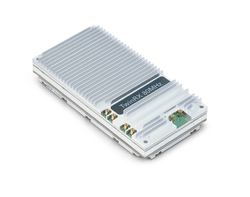
| − | + | |[[File:TwinRX large.png|250px|center]] | |
|} | |} | ||
Revision as of 19:37, 8 August 2016
Contents
Device Overview
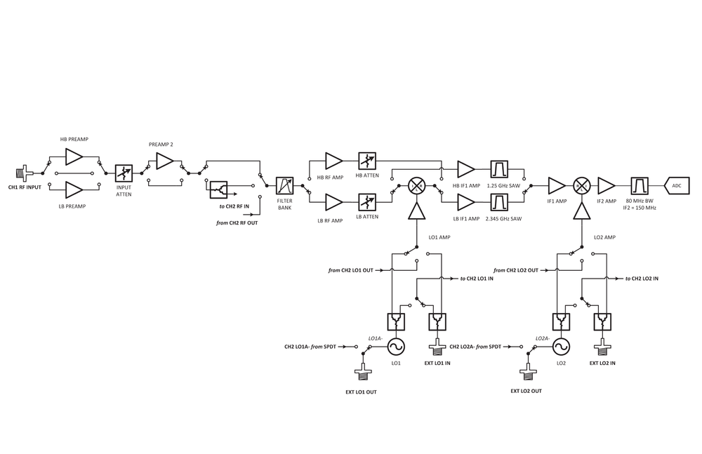
The TwinRX daughterboard for the USRP X Series SDR platform is a two-channel superheterodyne receiver designed for high performance spectrum monitoring and direction finding applications. The receiver is tunable from 10 MHz - 6 GHz and has 80 MHz of instantaneous bandwidth per channel, providing the versatility nessary to analyze a variety of signals in multiple bands of interest. Each channel has an independent RF signal chain with preampilifiers, preselectors, and two mixer stages for superior selectivity. Users can tune the two channels independently to simultaneously montior uplink and downlink communication with a combined bandwidth of 160 MHz. The ability to share the LO between channels across multiple daughterboards enables the phase-aligned operation required to implement scalable multi-channel phased-arrays. The receiver is capable of fast frequency hopping to detect frequency agile emitters. Configurable RF attenuation and preamplication allow users to optimize dynamic range in favor of noise figure for faint signals, or IP3 for stronger signals. UHD automatically configures the RF signal path for optimized performance in the pre-defined use cases, and provides the flexibility to adjust settings manually. Support for RFNoC on the X Series motherboard enables deterministic FPGA-accelerated computations for real-time spectrum analysis.
Key Features
|
Daughterboard Specifications
Features
- 2 superheterodyne frontends (2 receive)
- 80 MHz per channel
- Independent tuning
- LO Sharing Capability
- Coherent and phase-aligned operation
- Preselection Filters
- RF Shielding
Antennas
Receive: RX1 or RX2
Gains
- Receive Gains Range: 0-95dB
Bandwidths
- TwinRX: 80 MHz per channel ( 160 MHz total )
Sensors
- lo_locked: boolean for LO lock state
Ports
The TwinRX has six MMCX RF connectors on it.
| Connector | Description | Damage Threshold/Max Output |
|---|---|---|
| J1 | LO2 Export | 0 dBm output |
| J2 | LO2 Input | +20dBm input |
| J3 | LO1 Export | +5 dBm output |
| J4 | LO1 Input | +10dBm input |
| J5 | Antenna 1 connector (RX1) | +10 dBm input |
| J6 | Antenna 2 connector (RX2) | +10 dBm input |
Preselector Filters
| Band | Range |
|---|---|
| LB1 | 10 - 500 MHz |
| LB2 | 500 - 800 MHz |
| LB3 | 800 - 1.2 GHz |
| LB4 | 1.2 - 1.8 GHz |
| HB1 | 1.8 - 3.0 GHz |
| HB2 | 3.0 - 4.1 GHz |
| HB3 | 4.1 - 5.1 GHz |
| HB4 | 5.1 - 6.0 GHz |
- Each preselector filter has a ±40 MHz band overlap.
RF Specifications
Freq Range
- 10MHz - 6GHz
Noise Figure
| Frequency | Preamp Enabled |
|---|---|
| 10 MHz - 3 GHz | < 5 |
| 3 GHz - 5 GHz | < 4 |
| 5 GHz - 6 GHz | < 8 |
RX Third Order Intercept (dBm)
| Frequency | Full Scale = -45 dBm | Full Scale = -30 dBm | Full Scale = -20 dBm |
|---|---|---|---|
| 10 MHz - 1.8 GHz | -8 | -2 | 16 |
| 1.8 GHz - 3 GHz | -10 | -1 | 14 |
| 3 GHz - 6 GHz | -13 | -1 | 12 |
Phase Noise (dBc/Hz)
| Frequency Offset | 0.9 GHz | 2.4 GHz | 5.8 GHz |
|---|---|---|---|
| 10 kHz | -88 | -86 | -82 |
| 100 kHz | -105 | -107 | -103 |
| 1 MHz | -124 | -127 | -127 |
Hardware Specifications
- Ettus Research recommends to always use the latest stable version of UHD. Minimum UHD version is 3.10.0.0
TwinRX
- Current Hardware Revision: 2
- Minimum version of UHD required: 3.10.0.0
- Minimum version of GNU Radio required: 3.7.10
Environmental Specifications
Operating Temperature Range
- 0-40 °C
Operating Humidity Range
- 10% to 90% non-condensing
USRP Compatibility
- X Series only
Schematics
The TwinRX daughterboard is composed of two PCBs, the Intermediate Frequency (IF) board and the RF board. There are two functionally identical revisions of TwinRX at the moment. Please check the back of your TwinRX to see which you have. The schematics for TwinRX revision B should answer most possible questions. If you have any further questions please email [email protected].
TwinRX Revision A - (159685A-01)
- IF Board Revision B - (158671B-01L)
- RF Board Revision C - (156263C-01L)
TwinRX Revision B - (159685B-01)
- IF Board Revision C - (158671C-01L)
- RF Board Revision D - (156263D-01L)
File:TwinRX IF Board Rev C.pdf
File:TwinRX RF Board Rev D.pdf
RF Connectors
|
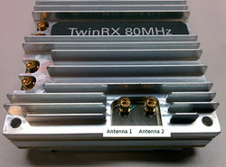
The antenna ports are MMCX connectors with 50 ohm input impedance. By default Antenna 1 (RX1) is routed to Channel 1 and Antenna 2 (RX2) to Channel 2. This routing can be changed to swap the antennas or to share a single antenna to both channels. The damage threshold for the antenna inputs is 10 dBm. In practice the available gain makes much lower input powers recommended for achieving the best dynamic range and noise figure. |
Local Oscillator Connectors
|
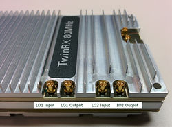
LO Sharing with Neighbour TwinRXs
| TwinRX (A Slot) | TwinRX (B Slot) |
|---|---|
| J1 LO2 Export | J2 LO2 Input |
| J2 LO2 Input | J1 LO2 Export |
| J3 LO1 Export | J4 LO1 Input |
| J4 LO1 Input | J3 LO1 Export |
Certifications
RoHS
As of December 1st, 2010 all Ettus Research products are RoHS compliant unless otherwise noted. More information can be found at http://ettus.com/legal/rohs-information


