X300/X310 Getting Started Guides
Contents
- 1 Kit Contents
- 2 Verify the Contents of Your Kit
- 3 You Will Need
- 4 Proper Care and Handling
- 5 Assembly
- 6 Install and Setup the Software Tools on Your Host Computer
- 7 Basic Connectivity
- 8 Upgrade to 10 Gigabit Ethernet or PCI-Express
- 9 Test and Verify the Operation of the USRP
- 10 Using the GPIO Expansion Kit USRP™ X300 and USRP X310
- 11 Technical Support and Community Knowledge Base
- 12 Legal Considerations
- 13 Sales and Ordering Support
- 14 Terms and Conditions of Sale
Kit Contents
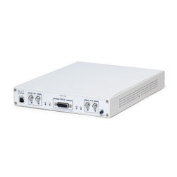
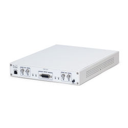
- USRP X300/X310
- 1 Gigabit Ethernet Cable
- SFP Adapter for 1 GigE
- Power Supply and US Cord
- USB 2.0 JTAG Debug Cable
- Four SMA-Bulkhead Cables
- Getting Started Guide
Verify the Contents of Your Kit
Make sure that your kit contains all the items listed above. If any items are missing, please contact your sales agent or Ettus Research Technical support immediately.
You Will Need
- A host computer with an available 1 GigE, 10 GigE, or PCI-Express port
Proper Care and Handling
All Ettus Research products are individually tested before shipment. The USRP™ is guaranteed to be functional at the time it is received by the customer. Improper use or handling of the USRP™ can easily cause the device to become non-functional. Listed below are some examples of actions which can prevent damage to the unit:
- Never allow metal objects to touch the circuit board while powered.
- Always properly terminate the transmit port with an antenna or 50Ω load.
- Always handle the board with proper anti-static methods.
- Never allow the board to directly or indirectly come into contact with any voltage spikes.
- Never allow any water, or condensing moisture, to come into contact with the boards.
- Always use caution with FPGA, firmware, or software modifications.
| Never apply more than -15 dBm of power into any RF input. | |
| Always use at least 30dB attenuation if operating in loopback configuration |
Assembly
The USRP X300/X310 and compatible RF daughterboards are shipped separately. To operate the device you will need to install the RF daughterboards and supplied bulkhead cables. This can be accomplished by removing the top plate of the USRP X300/X310, which is secured with two screws. After installation, the daughterboards and cables should be secured with the hardware provided. The device must be powered off when installing daughterboards to avoid potential damage. For a detailed step by step guide to assembling your X300/X310, see the USRP X Series Quick Start (Daughterboard Installation) guide.
Install and Setup the Software Tools on Your Host Computer
In order to use your Universal Software Radio Peripheral (USRP™), you must have the software tools correctly installed and configured on your host computer. A step-by-step guide for doing this is available at the Building and Installing the USRP Open-Source Toolchain (UHD and GNU Radio) on Linux, OS X and Windows Application Notes. Release 3.8.4 or later of the USRP Hardware Driver, UHD, is required. It is recommended to use the latest stable version of UHD that is available.
If you have a USB stick with the Live SDR Environment installed on it, then you may boot your host computer from that. The LiveUSB SDR Environment does not require anything to be installed on your host computer, and contains a Linux-based environment with the UHD software and the GNU Radio framework already installed. More information about the Live SDR Environment is available at the Live SDR Environment Getting Started Guides page.
Basic Connectivity
This USRP X300/X310 supports multiple, high-speed, low-latency interface options. This kit includes all of the components necessary to communicate with the device through a 1 Gigabit Ethernet interface. To setup the device, follow these basic instructions:
- Configure the host Ethernet adapter to use an IP address of "192.168.10.1" and a subnet mask of "255.255.255.0".
- Slide the SFP Adapter into the SFP "Port 0".
- Using the supplied Ethernet cable, connect the adapter to a host computer.
- The Green Led above SFP "Port 0" should illuminate.
- To test communications, ping the USRP device at address "192.168.10.2"
For more detailed on network setup, please see the section Interfaces and Connectivity of the X300/X310 Hardware Resources page. For help troubleshooting connectivity issues with your X3x0 device, see Troubleshooting X300/X310 Device Discovery Issues.
Upgrade to 10 Gigabit Ethernet or PCI-Express
The USRP X300/X310 also supports 10 Gigabit Ethernet and PCI-Express. To use these interfaces, we recommend our high-speed interface kits. For more information about these interface kits, please see the section Interfaces and Connectivity of the X300/X310 Hardware Resources page.
Test and Verify the Operation of the USRP
Once the software tools are installed on the host computer, or using the Live SDR Environment, verify the correct operation of the USRP by running the utility programs on the host computer. More information is available at the Verifying the Operation of the USRP Using UHD and GNU Radio Application Note.
Using the GPIO Expansion Kit USRP™ X300 and USRP X310
GPIO Expansion Kit Contents
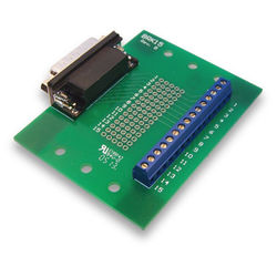
- 1 GPIO Breakout Board
- 1 DB-15, 1-meter cable
- GPIO Quick Reference
Circuit Protection
The GPIO signals exposed with this breakout kit are routed directly to the USRP device's FPGA with limited protection circuitry. However, the user must take precautionary measures to ensure input/output signals meet the specifications shown in this document. Over voltage, excess current draw, and other conditions can damage the USRP device and void the warranty. Special care should be taken when the USRP is powered off.
Mounting the GPIO Breakout Board
The GPIO breakout board can be mounted directly to the DB15 connector of a USRP ™ device, or mounted remotely with the cable provided in this kit. The screws on the DB15 connector of the breakout board must be removed to mount the board directly. For remote mounting, the breakout board is supplied with rubber standoffs to avoid scratching surfaces, and several through-holes for hard mounting with screws or other hardware (not provided).
Using GPIO with UHD, GNU Radio, and other Third-Party Frameworks
When used with UHD, or other third party frameworks that leverage UHD, the GPIO expansion can be controlled with simple API calls. For more information, on the C++ API, and examples of how to use the GPIO in frameworks such as GNU Radio, please see the Application Notes section of the Ettus Research Knowledge Base.
GPIO Specifications (3.3V Bank, LVCMOS)
| Parameter | Typical |
|---|---|
| Configured as Input | |
| Default Voltage Standard | 3.3V LVCMOS |
| Voltage High Threshold | 2.0V |
| Voltage Low Threshold | 0.8V |
| Voltage Input Limits (no damage) | -0.3V/3.45V |
| Configured as Output | |
| Voltage Standard | 3.3V LVCMOS |
| Voltage High Output | 2.8V |
| Voltage Low Output | 0.4V |
| Current Source Capability | 12 mA |
| Output Source Impedance | >33 ohms typical |
Technical Support and Community Knowledge Base
Technical support for USRP hardware is available through email only. If the product arrived in a nonfunctional state or you require technical assistance, please contact [email protected]. Please allow 24 to 48 hours for response by email, depending on holidays and weekends, although we are often able to reply more quickly than that.
We also recommend that you subscribe to the community mailing lists. The mailing lists have a responsive and knowledgeable community of hundreds of developers and technical users who are located around the world. When you join the community, you will be connected to this group of people who can help you learn about SDR and respond to your technical and specific questions. Often your question can be answered quickly on the mailing lists. Each mailing list also provides an archive of all past conversations and discussions going back many years. Your question or problem may have already been addressed before, and a relevant or helpful solution may already exist in the archive.
Discussions involving the USRP hardware and the UHD software itself are best addressed through the usrp-users mailing list at http://usrp-users.ettus.com.
Discussions involving the use of GNU Radio with USRP hardware and UHD software are best addressed through the discuss-gnuradio mailing list at https://lists.gnu.org/mailman/listinfo/discussgnuradio.
Discussions involving the use of OpenBTS® with USRP hardware and UHD software are best addressed through the openbts-discuss mailing list at https://lists.sourceforge.net/lists/listinfo/openbtsdiscuss.
The support page on our website is located at https://www.ettus.com/support. The Knowledge Base is located at https://kb.ettus.com.
Legal Considerations
Every country has laws governing the transmission and reception of radio signals. Users are solely responsible for insuring they use their USRP system in compliance with all applicable laws and regulations. Before attempting to transmit and/or receive on any frequency, we recommend that you determine what licenses may be required and what restrictions may apply.
- NOTE: This USRP product is a piece of test equipment.
Sales and Ordering Support
If you have any non-technical questions related to your order, then please contact us by email at [email protected], or by phone at +14086106399 (Monday-Friday, 8 AM - 5 PM, Pacific Time). Please be sure to include your order number and the serial number of your USRP.
Terms and Conditions of Sale
Terms and conditions of sale can be accessed online at the following link: http://www.ettus.com/legal/terms-and-conditions-of-sale


