USRP N Series Quick Start (Daughterboard Installation)
Contents
Introduction
Application Note Number: AN-5501
Authors: John Smith and Jane Smith
Organization: Ettus Research
Last Modified Date: 2016/04/15
Overview
This Quick Start is meant to show you how to put together your new N200/N210. We will start with installing a WBX daughterboard and go all the way to being able to ping the device, performing a quick software probe to verify hardware components and finally running a simple FFT demo. This Quick Start does not cover the installation of software on the host computer. If you have not installed UHD/Gnuradio on your system, please reference the Building and Installing the USRP Open-Source Toolchain (UHD and GNU Radio) on Linux, OS X and Windows Application Notes. You may also use the Live SDR Environment to perform the verification steps for your USRP. Detailed information on the Live SDR Environment is available at the Live SDR Environment Getting Started Guides page.
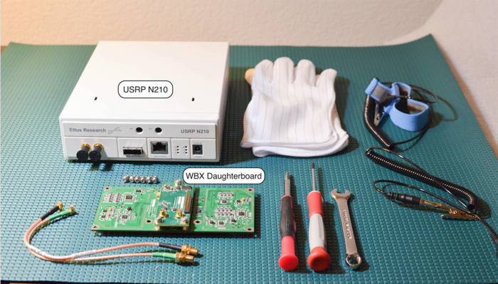
Tools Required
- Philips Screwdriver
- Torx Screwdriver
- 5/16” wrench
- ESD Mat
- ESD Wrist strap
- ESD Gloves
Pre-installed Software
- UHD Latest (http://code.ettus.com/redmine/ettus/projects/uhd/wiki)
- GNU Radio (http://gnuradio.org/redmine/projects/gnuradio/wiki/InstallingGR)
Parts Checklist
- 1 x USRP N200/N210
- 1 x Power Supply and US Cord
- 1 x Gigabit Ethernet Cable
- 2 x SMA-Bulkhead Cables (SMA to MCX)
- 1 x WBX Daughterboards
- 6 x Daughterboard Screws
- One or more Antennas
Proper Handling
All Ettus Research products are individually tested before shipment. The USRP™ is guaranteed to be functional at the time it is received by the customer. Improper use or handling of the USRP™ can easily cause the device to become non-functional. Ettus Research recommends you perform the installation with no power to the USRP and using ESD equipment. Listed below are some examples of actions which can prevent damage to the unit:
- Never apply more than -15 dBm of power into any RF input.
- Never allow metal objects to touch the circuit board while powered.
- Always properly terminate the transmit port with an antenna or 50Ω load.
- Always handle the board with proper anti-static methods.
- Never allow the board to directly or indirectly come into contact with any voltage spikes.
- Never allow any water, or condensing moisture, to come into contact with the boards.
- Always use caution with FPGA, firmware, or software modifications.
- Always use at least 30dB attenuation if operating in loopback configuration
Installation Process
Step 1
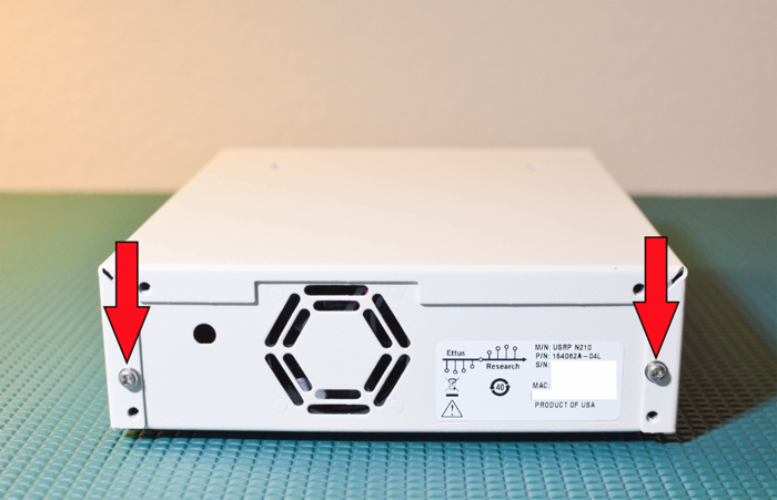
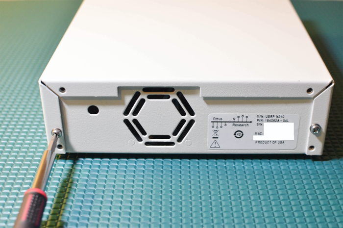
Unscrew the 2 screws on the back of the USRP and remove the top cover. (Lift up about 15 degrees and wiggle back as there is a flange on the front part of the cover)
Step 2
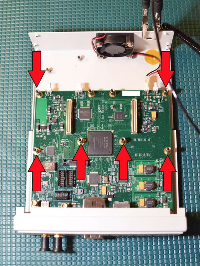
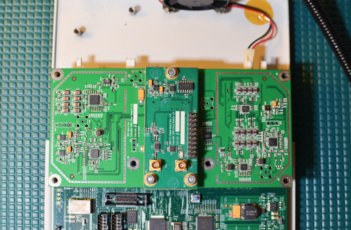
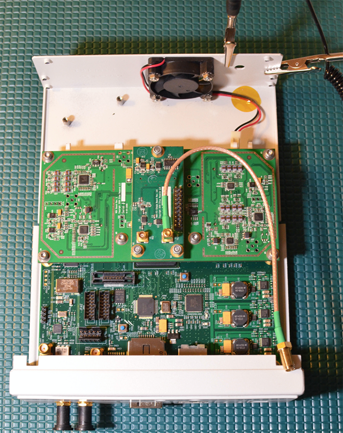
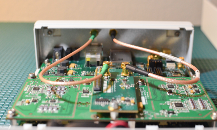
Line up the 6 of the 8 screw holes on the Daughterboard with the USRP Motherboard standoffs (they only go one way). The WBX will only use 6 of the mounting points.
Step 3
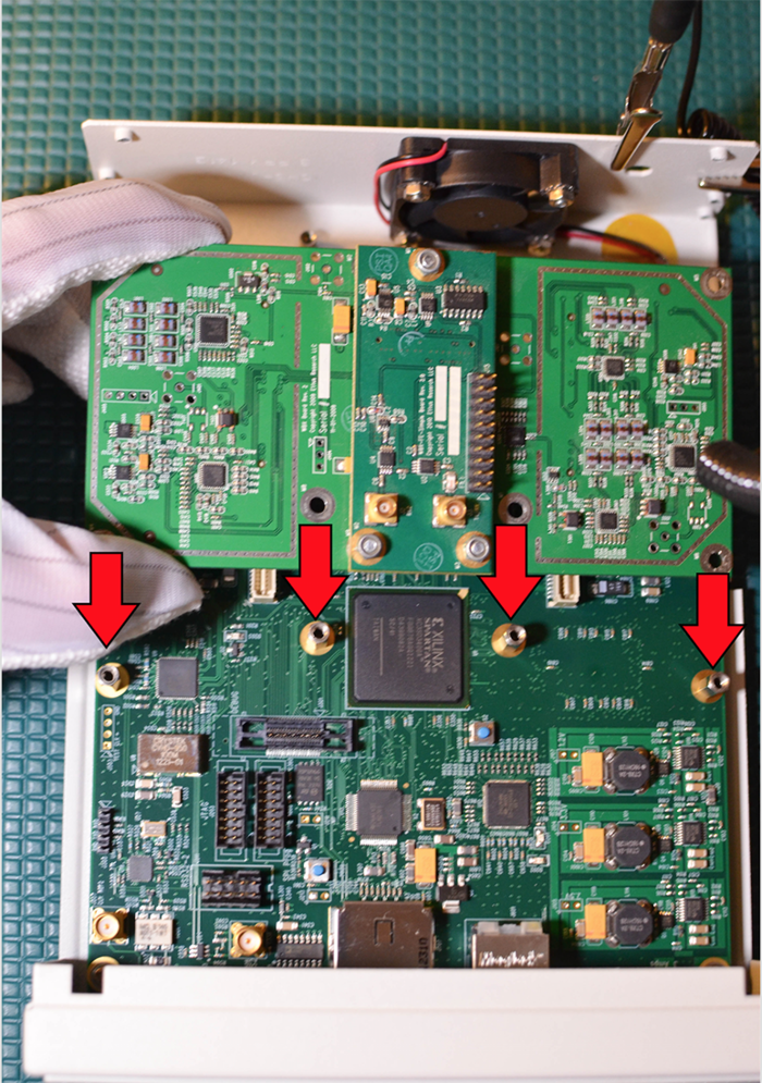
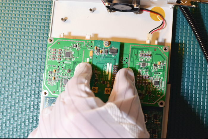
After you have aligned the Daughterboard correctly you can press the Daughterboard on to the connectors below them (you will feel them snap into place).
Step 4
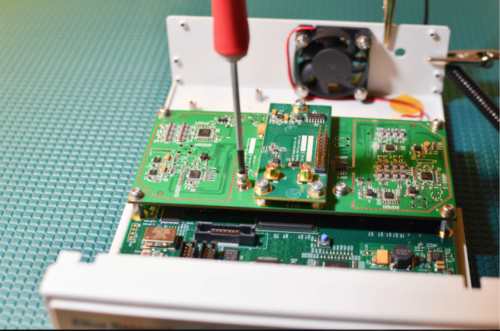
Put 6 of the screws provided in the daughterboard
Step 5
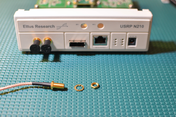
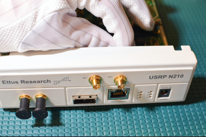
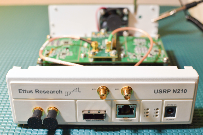
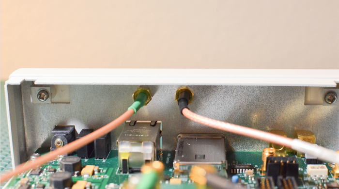
It is recommended to connect the bulkhead cables one at a time to avoid confusion. Note which front panel point (RF1, RF2) you install each connector from the daughterboard to (TX/RX, RX2).
Step 6
Install USRP cover with screws
Step 8
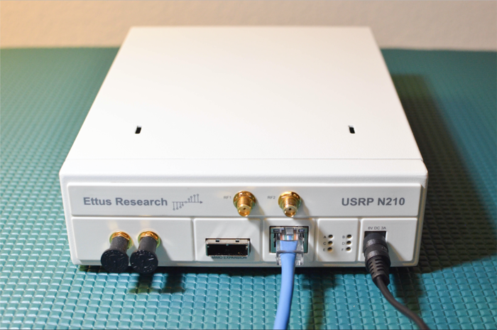
Connect the Gigabit Ethernet cable and power cord provided (do not plug in the power adapter to the wall outlet)
Step 7
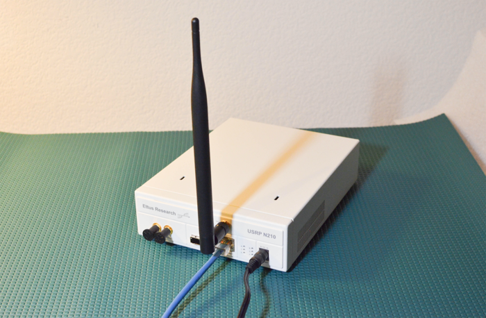
Attach any Antennas you may have purchased
Step 9
On the computer(host) you plan to use to connect to the USRP set the Ethernet adapter to have an IP address of 192.168.10.1 with a subnet mask of 255.255.255.0. Connect the other end of the Gigabit Ethernet cable to your computer.
- Note: The N200/N210 only supports 1 GigE ethernet speeds
Step 10
Power on the USRP (by plugging in the power adapter into wall outlet)
Step 11
Ping the device from host computer:
$ ping 192.168.10.2
Step 15
Assuming you have properly installed the UHD driver (http://code.ettus.com/redmine/ettus/projects/uhd/wiki) you can now run this command in a terminal/command window:
$ uhd_usrp_probe
This will tell you about the hardware inside of your USRP. Example output below.
   $ uhd_usrp_probe
   linux; GNU C++ version 4.8.4; Boost_105400; UHD_003.010.git-156-g2d68f228

   -- Opening a USRP2/N-Series device...
   -- Current recv frame size: 1472 bytes
   -- Current send frame size: 1472 bytes
   -- Detecting internal GPSDO.... No GPSDO found
     _____________________________________________________
    /
   |       Device: USRP2 / N-Series Device
   |     _____________________________________________________
   |    /
   |   |       Mboard: N210r4
   |   |   hardware: 2577
   |   |   mac-addr: 00:00:00:00:00:00
   |   |   ip-addr: 192.168.10.2
   |   |   subnet: 255.255.255.255
   |   |   gateway: 255.255.255.255
   |   |   gpsdo: none
   |   |   serial: xxxxxxx
   |   |   FW Version: 12.4
   |   |   FPGA Version: 11.1
   |   |
   |   |   Time sources: none, external, _external_, mimo
   |   |   Clock sources: internal, external, mimo
   |   |   Sensors: mimo_locked, ref_locked
   |   |     _____________________________________________________
   |   |    /
   |   |   |       RX DSP: 0
   |   |   |   Freq range: -50.000 to 50.000 MHz
   |   |     _____________________________________________________
   |   |    /
   |   |   |       RX DSP: 1
   |   |   |   Freq range: -50.000 to 50.000 MHz
   |   |     _____________________________________________________
   |   |    /
   |   |   |       RX Dboard: A
   |   |   |   ID: WBX, WBX + Simple GDB (0x0053)
   |   |   |   Serial: xxxxxxxx
   |   |   |     _____________________________________________________
   |   |   |    /
   |   |   |   |       RX Frontend: 0
   |   |   |   |   Name: WBXv2 RX+GDB
   |   |   |   |   Antennas: TX/RX, RX2, CAL
   |   |   |   |   Sensors: lo_locked
   |   |   |   |   Freq range: 68.750 to 2200.000 MHz
   |   |   |   |   Gain range PGA0: 0.0 to 31.5 step 0.5 dB
   |   |   |   |   Bandwidth range: 40000000.0 to 40000000.0 step 0.0 Hz
   |   |   |   |   Connection Type: IQ
   |   |   |   |   Uses LO offset: No
   |   |   |     _____________________________________________________
   |   |   |    /
   |   |   |   |       RX Codec: A
   |   |   |   |   Name: xxxxxxxx
   |   |   |   |   Gain range digital: 0.0 to 6.0 step 0.5 dB
   |   |   |   |   Gain range fine: 0.0 to 0.5 step 0.1 dB
   |   |     _____________________________________________________
   |   |    /
   |   |   |       TX DSP: 0
   |   |   |   Freq range: -50.000 to 50.000 MHz
   |   |     _____________________________________________________
   |   |    /
   |   |   |       TX Dboard: A
   |   |   |   ID: WBX (0x0052)
   |   |   |   Serial: xxxxxxxx
   |   |   |     _____________________________________________________
   |   |   |    /
   |   |   |   |       TX Frontend: 0
   |   |   |   |   Name: WBXv2 TX+GDB
   |   |   |   |   Antennas: TX/RX, CAL
   |   |   |   |   Sensors: lo_locked
   |   |   |   |   Freq range: 68.750 to 2200.000 MHz
   |   |   |   |   Gain range PGA0: 0.0 to 25.0 step 0.1 dB
   |   |   |   |   Bandwidth range: 40000000.0 to 40000000.0 step 0.0 Hz
   |   |   |   |   Connection Type: IQ
   |   |   |   |   Uses LO offset: No
   |   |   |     _____________________________________________________
   |   |   |    /
   |   |   |   |       TX Codec: A
   |   |   |   |   Name: xxxxxxxx
   |   |   |   |   Gain Elements: None
UHD FFT
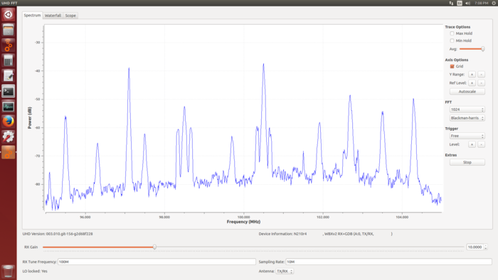
Try the UHD_FFT demo that comes with GNU Radio
1. Connect an antenna to TX/RX
2.From the terminal/command window:
$ uhd_fft --args "addr=192.168.10.2" -A TX/RX -s 10e6 -g 10 -f 100e6
Success
Congratulations! You have successfully setup and verified your new USRP N200/N210. A more detailed verification guide is at the Verifying the Operation of the USRP Using UHD and GNU Radio application note. For additional step-by-step guides to using your USRP N200/N210, see the Application Notes section of the Ettus Research Knowledge Base.

