USRP X Series Quick Start (Daughterboard Installation)
Contents
Overview
This Quick Start is meant to show you how to put together your new X300/310. We will start at the point when you have yet to unpack the boxes and go all the way to being able to ping the device, performing a quick software probe to verify hardware components and finally running a simple FFT demo. This Quick Start does not cover the installation of software on the host computer.
Tools Required
- Philips Screwdriver
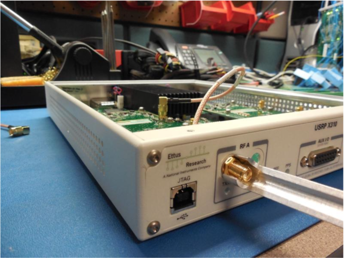
- 5/16” wrench
Pre-installed Software
- UHD Latest (http://code.ettus.com/redmine/ettus/projects/uhd/wiki)
- GNU Radio (http://gnuradio.org/redmine/projects/gnuradio/wiki/InstallingGR)
Box Contents
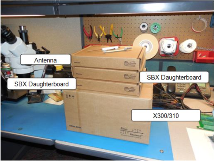
USRP Box
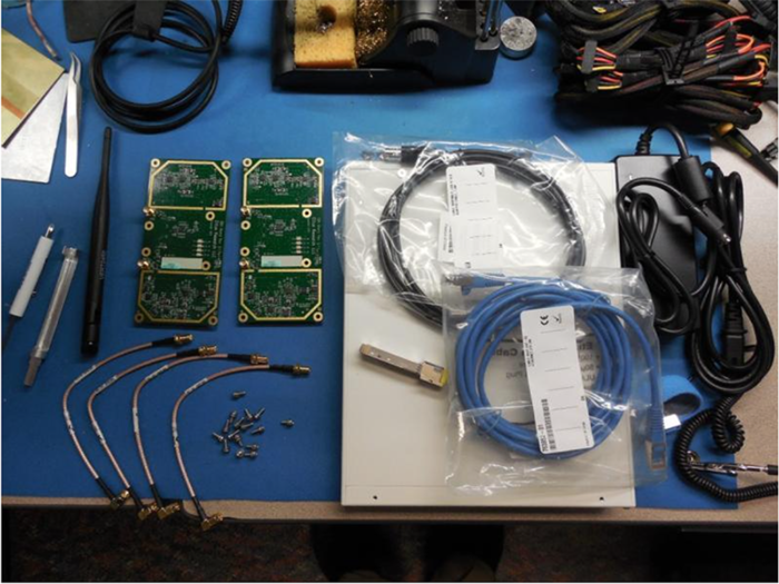
- 1 x USRP X300/X310
- 1 x SFP Adapter for 1 GigE
- 1 x Power Supply and US Cord
- 1 x USB 2.0 JTAG Debug Cable
- 1 x Gigabit Ethernet Cable
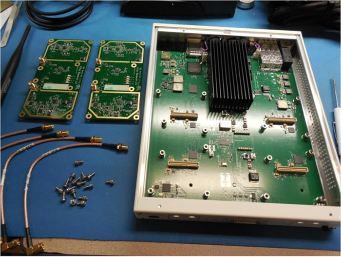
- 4 x SMA-Bulkhead Cables
- 16 x Daughterboard Screws
Daughterboard Boxes
- 2 x SBX Daughterboards
Antenna Boxes
- One or more Antennas
Proper Handling
Ettus Research recommends you perform the installation with no power to the USRP and using ESD equipment.
Installation Process
Step 1
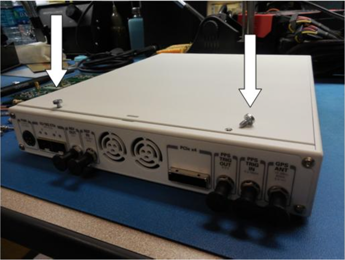
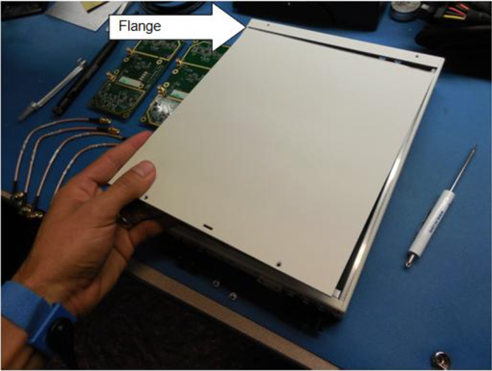
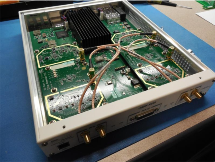
Unscrew the 2 screws on the top of the USRP and remove cover. (Lift up about 15 degrees and wiggle back as there is a flange on the front part of the cover)
Step 2
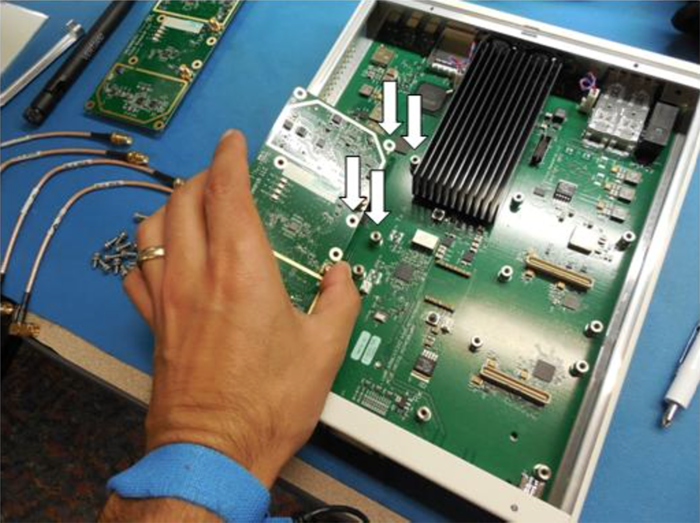
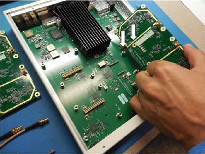
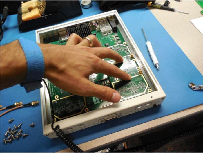
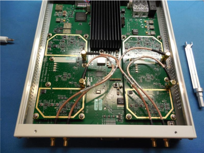
Line up the 8 screw holes on the Daughterboard with the USRP Motherboard standoffs (they only go one way).
Step 3
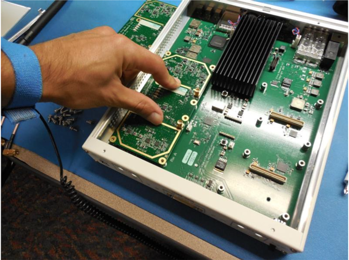
After you have aligned the Daughterboard correctly you can press the Daughterboard on to the connectors below them (you will feel them snap into place).
Step 4
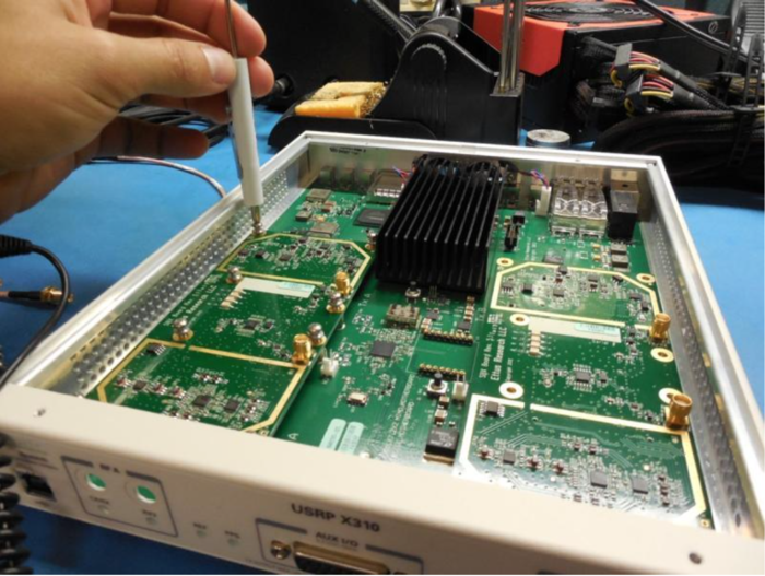
Put 8 of the screws provided in the daughterboard
Step 5
Repeat steps 2- 4 for the second Daughterboard
Step 6
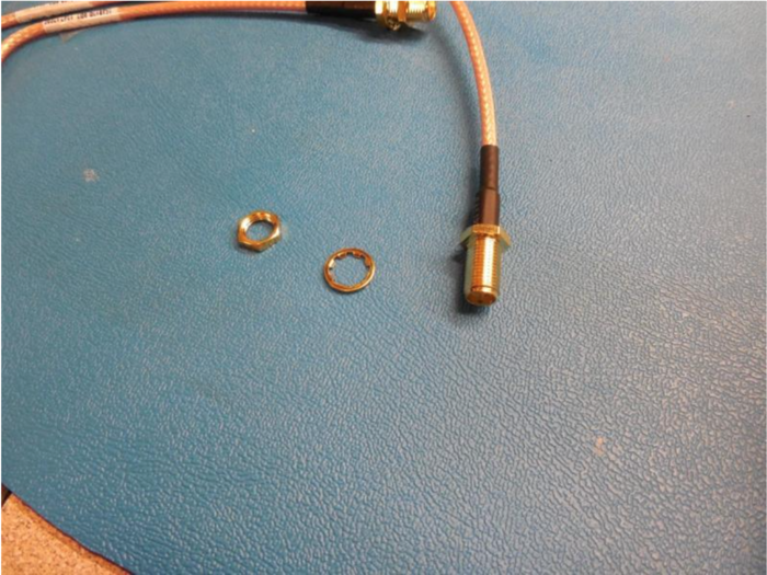
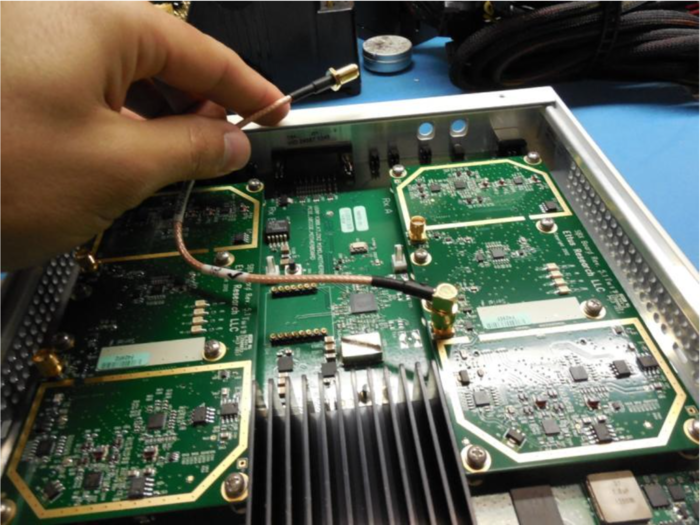
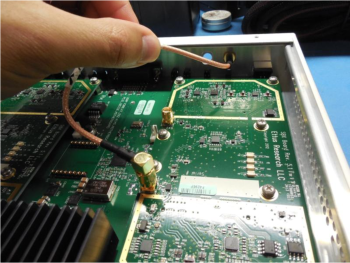
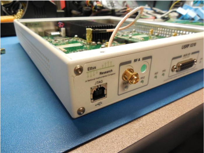
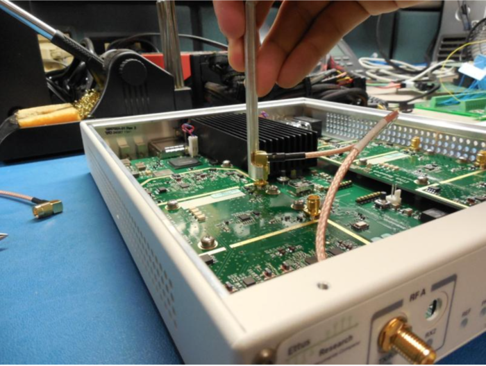
It is recommended to connect the bulkhead cables one at a time to avoid confusion. The Daughterboards and front panel of the X300/310 are clearly labeled as to which cable goes where.
Step 7
Repeat step 6 for the other bulkhead cables
Step 8
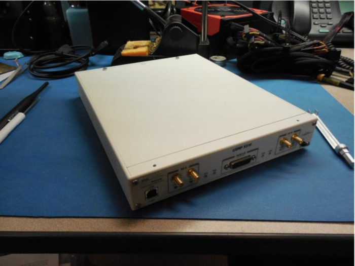
Install USRP cover with screws
Step 9
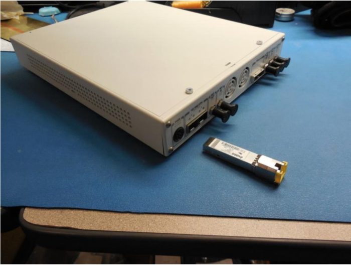
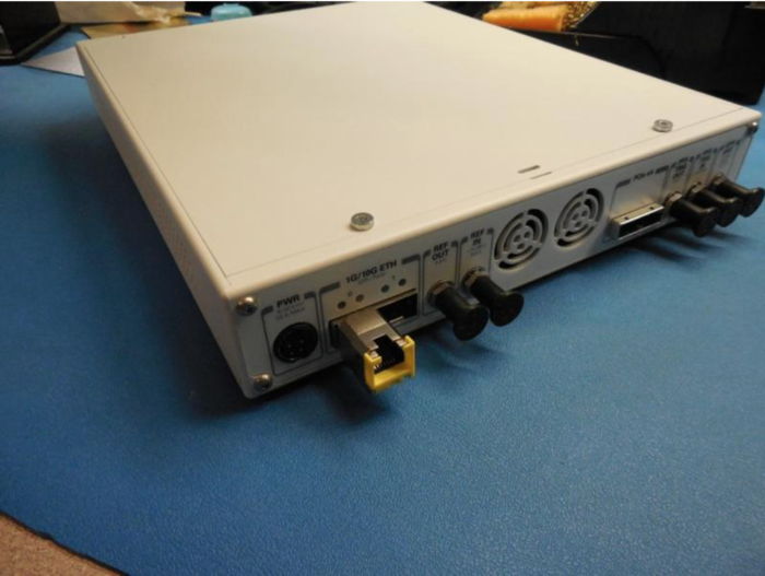
Connect the SFP 1 GigE adapter into USRP SFP port 0
Step 10
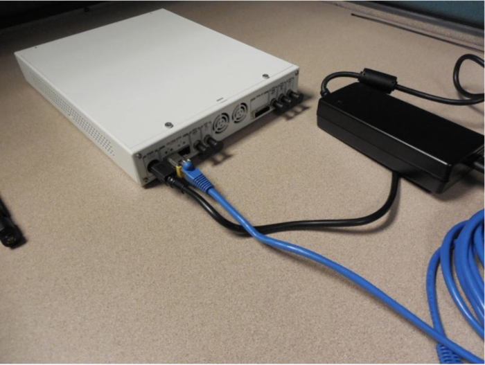
Connect the Gigabit Ethernet cable and power cord provided
Step 11
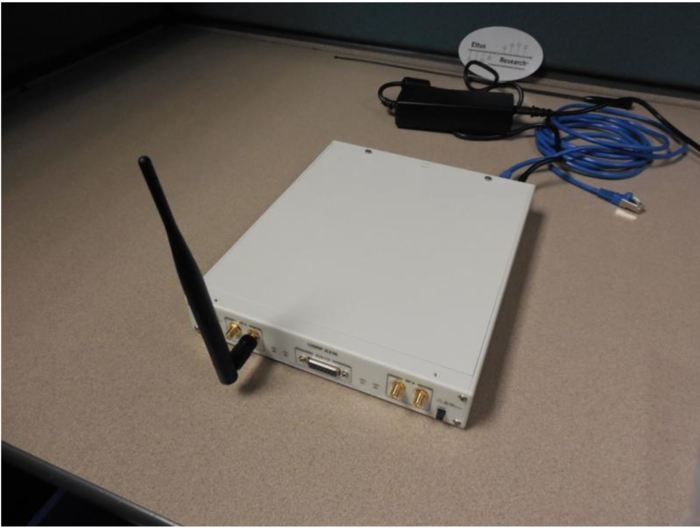
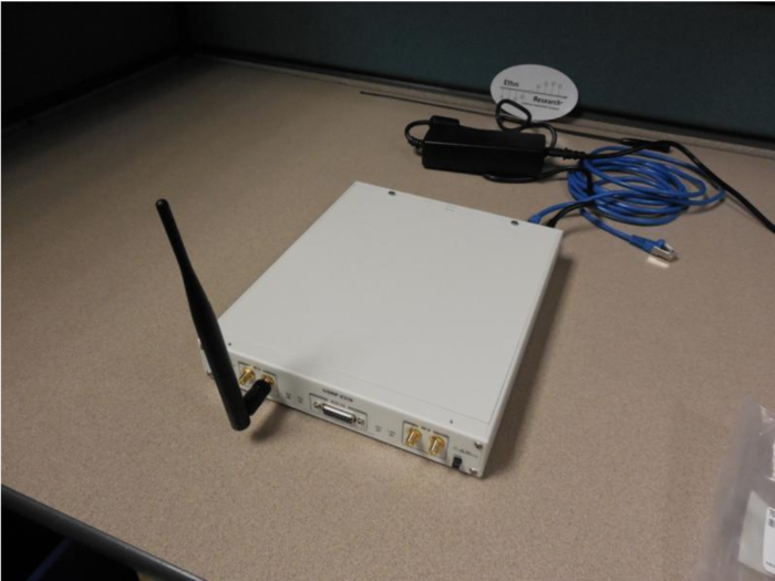
Attach any Antennas you may have purchased
Step 12
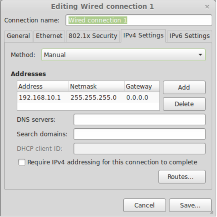
On the computer(host) you plan to use to connect to the USRP set the Ethernet adapter to have an IP address of 192.168.10.1 with a subnet mask of 255.255.255.0. Connect the other end of the Gigabit Ethernet cable to your computer.
Step 13
Power on the USRP (button on the front right of the USRP)
Step 14
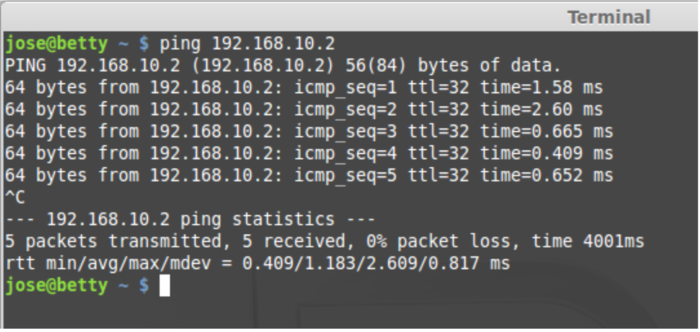
Ping the device from host computer:
$ ping 192.168.10.2
Step 15
Assuming you have properly installed the UHD driver (http://code.ettus.com/redmine/ettus/projects/uhd/wiki) you can now run this command in a terminal/command window: $ uhd_usrp_probe. This will tell you about the hardware inside of your USRP. The output will look like the following:
   $ uhd_usrp_probe
   linux; GNU C++ version 4.8.4; Boost_105400; UHD_003.010.git-202-g9e0861e1

   -- X300 initialization sequence...
   -- Determining maximum frame size... 1472 bytes.
   -- Setup basic communication...
   -- Loading values from EEPROM...
   -- Setup RF frontend clocking...
   -- Radio 1x clock:200
   -- Detecting internal GPSDO.... No GPSDO found
   -- Initialize Radio0 control...
   -- Performing register loopback test... pass
   -- Initialize Radio1 control...
   -- Performing register loopback test... pass
     _____________________________________________________
    /
   |       Device: X-Series Device
   |     _____________________________________________________
   |    /
   |   |       Mboard: X300
   |   |   revision: 7
   |   |   revision_compat: 7
   |   |   product: 30518
   |   |   mac-addr0: ff:ff:ff:ff:ff:ff
   |   |   mac-addr1: ff:ff:ff:ff:ff:ff
   |   |   gateway: 255.255.255.255
   |   |   ip-addr0: 255.255.255.255
   |   |   subnet0: 255.255.255.255
   |   |   ip-addr1: 255.255.255.255
   |   |   subnet1: 255.255.255.255
   |   |   ip-addr2: 255.255.255.255
   |   |   subnet2: 255.255.255.255
   |   |   ip-addr3: 255.255.255.255
   |   |   subnet3: 255.255.255.255
   |   |   serial: FFFFFFF
   |   |   FW Version: 4.0
   |   |   FPGA Version: 20.0
   |   |
   |   |   Time sources: internal, external, gpsdo
   |   |   Clock sources: internal, external, gpsdo
   |   |   Sensors: ref_locked
   |   |     _____________________________________________________
   |   |    /
   |   |   |       RX DSP: 0
   |   |   |   Freq range: -100.000 to 100.000 MHz
   |   |     _____________________________________________________
   |   |    /
   |   |   |       RX DSP: 1
   |   |   |   Freq range: -100.000 to 100.000 MHz
   |   |     _____________________________________________________
   |   |    /
   |   |   |       RX Dboard: A
   |   |   |   ID: SBX (0x0054)
   |   |   |   Serial: FFFFFF
   |   |   |     _____________________________________________________
   |   |   |    /
   |   |   |   |       RX Frontend: 0
   |   |   |   |   Name: SBXv3 RX
   |   |   |   |   Antennas: TX/RX, RX2, CAL
   |   |   |   |   Sensors: lo_locked
   |   |   |   |   Freq range: 400.000 to 4400.000 MHz
   |   |   |   |   Gain range PGA0: 0.0 to 31.5 step 0.5 dB
   |   |   |   |   Bandwidth range: 40000000.0 to 40000000.0 step 0.0 Hz
   |   |   |   |   Connection Type: IQ
   |   |   |   |   Uses LO offset: No
   |   |   |     _____________________________________________________
   |   |   |    /
   |   |   |   |       RX Codec: A
   |   |   |   |   Name: ads62p48
   |   |   |   |   Gain range digital: 0.0 to 6.0 step 0.5 dB
   |   |     _____________________________________________________
   |   |    /
   |   |   |       RX Dboard: B
   |   |   |   ID: SBX (0x0054)
   |   |   |   Serial: FFFFFF
   |   |   |     _____________________________________________________
   |   |   |    /
   |   |   |   |       RX Frontend: 0
   |   |   |   |   Name: SBXv3 RX
   |   |   |   |   Antennas: TX/RX, RX2, CAL
   |   |   |   |   Sensors: lo_locked
   |   |   |   |   Freq range: 400.000 to 4400.000 MHz
   |   |   |   |   Gain range PGA0: 0.0 to 31.5 step 0.5 dB
   |   |   |   |   Bandwidth range: 40000000.0 to 40000000.0 step 0.0 Hz
   |   |   |   |   Connection Type: IQ
   |   |   |   |   Uses LO offset: No
   |   |   |     _____________________________________________________
   |   |   |    /
   |   |   |   |       RX Codec: B
   |   |   |   |   Name: ads62p48
   |   |   |   |   Gain range digital: 0.0 to 6.0 step 0.5 dB
   |   |     _____________________________________________________
   |   |    /
   |   |   |       TX DSP: 0
   |   |   |   Freq range: -100.000 to 100.000 MHz
   |   |     _____________________________________________________
   |   |    /
   |   |   |       TX DSP: 1
   |   |   |   Freq range: -100.000 to 100.000 MHz
   |   |     _____________________________________________________
   |   |    /
   |   |   |       TX Dboard: A
   |   |   |   ID: SBX (0x0055)
   |   |   |   Serial: FFFFFF
   |   |   |     _____________________________________________________
   |   |   |    /
   |   |   |   |       TX Frontend: 0
   |   |   |   |   Name: SBXv3 TX
   |   |   |   |   Antennas: TX/RX, CAL
   |   |   |   |   Sensors: lo_locked
   |   |   |   |   Freq range: 400.000 to 4400.000 MHz
   |   |   |   |   Gain range PGA0: 0.0 to 31.5 step 0.5 dB
   |   |   |   |   Bandwidth range: 40000000.0 to 40000000.0 step 0.0 Hz
   |   |   |   |   Connection Type: QI
   |   |   |   |   Uses LO offset: No
   |   |   |     _____________________________________________________
   |   |   |    /
   |   |   |   |       TX Codec: A
   |   |   |   |   Name: ad9146
   |   |   |   |   Gain Elements: None
   |   |     _____________________________________________________
   |   |    /
   |   |   |       TX Dboard: B
   |   |   |   ID: SBX (0x0055)
   |   |   |   Serial: FFFFFF
   |   |   |     _____________________________________________________
   |   |   |    /
   |   |   |   |       TX Frontend: 0
   |   |   |   |   Name: SBXv3 TX
   |   |   |   |   Antennas: TX/RX, CAL
   |   |   |   |   Sensors: lo_locked
   |   |   |   |   Freq range: 400.000 to 4400.000 MHz
   |   |   |   |   Gain range PGA0: 0.0 to 31.5 step 0.5 dB
   |   |   |   |   Bandwidth range: 40000000.0 to 40000000.0 step 0.0 Hz
   |   |   |   |   Connection Type: QI
   |   |   |   |   Uses LO offset: No
   |   |   |     _____________________________________________________
   |   |   |    /
   |   |   |   |       TX Codec: B
   |   |   |   |   Name: ad9146
   |   |   |   |   Gain Elements: None
UHD FFT
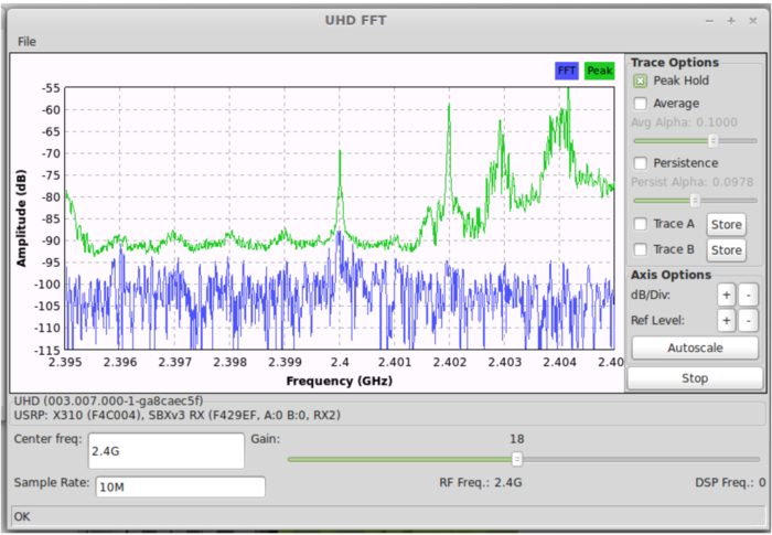
Try the UHD_FFT demo that comes with GNU Radio
1. Connect one antenna to RX2 on the left Daughterboard (Daughterboard A)
2.From the terminal/command window:
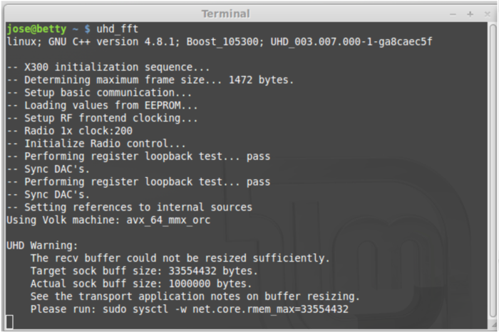
$ uhd_fft

