Interrogating Passive Wireless SAW Sensors with the USRP
Contents
- 1 Application Note Number
- 2 Revision History
- 3 Interrogating Passive, Wireless SAW Sensors with the USRP B200mini
- 3.1 Challenge
- 3.2 Solution
- 3.3 Introduction
- 3.4 Consortium for Applied Acoustoelectronic Technology (CAAT) - University of Central Florida
- 3.5 Passive, Wireless SAW Sensors
- 3.6 USRP FPGA Modifications and Software
- 3.7 USRP System
- 3.8 Wireless Temperature Measurements with the USRP
- 3.9 Conclusion
- 3.10 References
- 3.11 Contact Information
Application Note Number
AN-188
Revision History
| Date | Author | Details |
|---|---|---|
| 2016-05-01 | Trip Humphries | Initial creation |
| 2016-05-09 | Trip Humphries | Version 1 |
Interrogating Passive, Wireless SAW Sensors with the USRP B200mini
Authors: James 'Trip' Humphries, Jose Figueroa, Mark Gallagher, Daniel Gallagher, Arthur Weeks, Donald Malocha
Ettus Research Products Used: USRP B200mini
Research Institution: University of Central Florida, Orlando, FL, USA
Laboratory: Consortium for Applied Acoustoelectronic Technology (CAAT)
Application Area: Wireless Sensors
Challenge
Develop a wide-band transceiver to interrogate passive, wireless surface acoustic wave (SAW) sensors at 915MHz using a commercially available software radio platform.
Solution
The Ettus USRP B200mini was utilized to interrogate wireless SAW sensors by modifying the FPGA design to implement a synchronous, pulsed mode interrogator and utilize the entire 56MHz bandwidth of the B200mini.
Introduction
Typical interrogator design for wireless SAW sensor systems require many discrete components and lengthy build times, making it difficult to rapidly adapt to sensor designs in a research environment. We have employed the USRP B200mini as a SAW sensor interrogation system. Interrogation of wideband orthogonal frequency coded (OFC) SAW sensors imposes strict requirements on the timing and synchronization of the transceiver. The USRP FPGA has been modified to operate in a synchronous, pulsed mode of operation, allowing rapid data acquisition and the full 56MHz bandwidth of the AD9364 to be utilized. Data from the USRP is passed to a custom matched filter correlator routine to extract sensor parameters. The system is capable of interrogating multiple sensors, simultaneously. Demonstration of the system is accomplished by wirelessly interrogating SAW sensors at 915MHz and extracting temperature. A photograph of the system is shown in Figure 1.
-
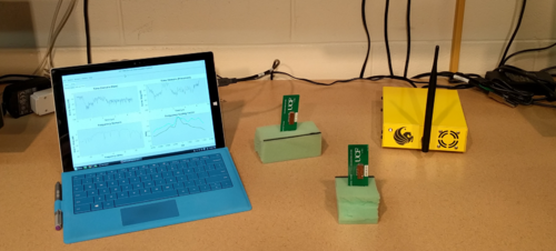 Figure 1: Photograph of passive, wireless SAW sensor system using the USRP B200mini. On the left is the host computer to handle the USRP interface and perform post-processing to extract the sensor parameters. In the center is the are two wireless SAW sensors. On the right is the interrogator system and USRP in a custom enclosure.
Consortium for Applied Acoustoelectronic Technology (CAAT) - University of Central Florida
The Consortium for Applied Acoustoelectronic Technology (CAAT) is a part of the University of Central Florida (UCF), in Orlando, FL. UCF is a comprehensive university with an enrollment of over 60,000 students. The UCF College of Engineering and Computer Science (CECS) supports multidisciplinary engineering research; offering advanced degrees at the MS and PhD levels. The focus and expertise of CAAT is surface acoustic wave (SAW) devices and applications. Currently, CAAT is developing passive, wireless sensors based on SAW technology. The sensors are identified using an encoding technique known as orthogonal frequency coding (OFC). The sensors do not require an energy source (battery or other) and can be read from many meters away. Temperature, strain, and hydrogen sensors (among others) have been demonstrated wirelessly with this technology.
Passive, Wireless SAW Sensors
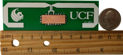
SAW devices have many inherent properties that make them useful as sensors. Not only are they rugged to environmental extremes such as high temperature and radiation, but they can be operated wirelessly and passively (requires no power source or energy harvesting onboard the sensor). An interrogation signal is transmitted by the radio, illuminating all the SAW sensor tags simultaneously. Each SAW sensor reflects the received interrogation signal and is very similar to a RADAR system. The use of the SAW device allows the reflection to be engineered to encode the device ID (code) and measurand via changes in frequency, phase, or magnitude. The resulting changes can be measured and correlated to some measurement such as temperature, strain, or gas concentration. A SAW temperature sensor with integrated antenna is shown in Figure 2.
Orthogonal frequency coding (OFC) can be implemented on a SAW platform by placing an array of reflector gratings in the path of the surface wave [1]. Each grating is assigned a center frequency which is orthogonal to all other gratings in the reflector array. OFC chips that are not synchronous to an incoming signal will appear nearly transparent to that frequency. The chips are shuffled in time to create a unique code, which identifies the sensor. Each sensor code is also given a discrete time slot and time gating during post-processing can be used to improve the sensor SNR. An illustration of a SAW device with OFC is given in Figure 3.
-
 Figure 3: Illustration of a SAW OFC sensor tag. A signal input to the antenna is converted to an acoustic wave by the SAW transducer (left). The signal propagates to the OFC chips (right) and is reflected back to the transducer where it is re-radiated for reception on the USRP. The received signal is noise-like and is processed by a match-filter correlator to extract sensor parameters.
USRP FPGA Modifications and Software
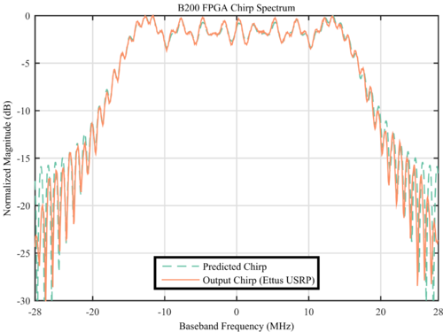
Modifications were made to the USRP FPGA to incorporate custom functionality in both the transmit and receive chains. On the transmit side, an interrogation signal generator was implemented. It generates a linear FM chirp with a bandwidth of 35MHz and time length of 1µs. The receiver was modified to synchronize to the transmit signal (start listening for sensor response after the interrogation signal has finished transmitting) and incorporate a listen window. The receiver listens for 9.15µs and stores those samples into a RAM buffer. The samples are then read back from the RAM buffer at a slow rate such that the full 56MHz bandwidth of the system can be utilized without saturating the sample bus (USB3.0). Real time post processing is not required for this application. A block diagram outlining the FPGA modifications is shown in Figure 4. A plot comparing the predicted and generated chirp spectrums is also given in Figure 5.
-
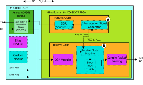 Figure 4: Block diagram of the USRP B200 showing the custom FPGA modifications. The open-source FPGA code was able to be modified to fit the specific requirements of interrogating SAW sensors. The interrogation signal generator (A) outputs a linear FM chirp that is 1us long and has a 35MHz bandwidth. The receiver modifications (B) buffers 512 samples after the interrogation signal has finished.
The USRP was integrated with a custom matched-filter correlation software package in Python using the GNU Radio Python API [2]. A set of matched filters is generated for each sensor in the system, where each matched filter corresponds to a specific temperature of the sensor (the user specifies the minimum and maximum temperatures as well as the temperature resolution). The matched filters are scaled using a frequency scaling factor (FSF), based on calibrated sensor parameters. The received sensor signal is correlated with each matched filter. The matched filter which yields the maximum correlation peak corresponds to the temperature of the current sensor being processed. Interrogation of a single sensor and extraction of the sensor temperature can be done in approximately 10-15ms with this setup. A block diagram of the implemented software is shown in Figure 6.
-
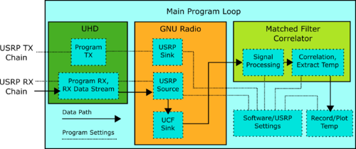 Figure 6: Block diagram of the software implemented on the host computer for data capture and post processing. UHD handles the data transfer and programming of the USRP. GNU Radio provides useful programming and DSP blocks for the USRP data. A custom Python block was implemented in GNU Radio ('UCF Sink') which stores a requested number of samples to a memory vector which can be copied to the host program when needed. The received data is processed by a matched filter correlator to extract the temperature or other measurand.
USRP System
The full SAW sensor interrogation system included extra components to improve the transceiver performance. An amplifier was added to the transmit chain to increase the output power of the transmitter to >+20dBm. This allows the SAW sensors to be interrogated at a farther range. With this output power, current sensors can be detected at a range of 5 meters (16 feet) or more with a high gain antenna. In addition to the amplifier, an RF switch was incorporated which switches between the TRX and RX2 ports on the USRP. This allows a single antenna to be used for transmission and reception (instead of one antenna for each port). This also has the added benefit of eliminating the direct response between the two antennas from the interrogation pulse which can saturate the receiver and distort the received signal response. The switch is controlled by the USRP GPIO pins connected to the FPGA. Finally, a custom enclosure was designed to house the SAW sensor interrogation system. Photographs of the system are shown in Figure 7 and Figure 8.
| USRP: | B200mini |
| Amplifier (TX): | Mini-Circuits ZX60-H122+ |
| RF Switch: | Mini-Circuits ZFSWA2-63DR+ |
| Enclosure: | Custom Design - Manufactured by Protocase, Inc. |
-
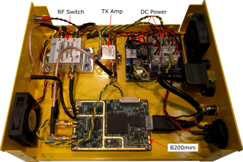 Figure 7: Photograph of the USRP SAW sensor interrogation system with added components. An amplifier increases the output power to greater than +20dBm while an RF switch allows only a single antenna to be used for both transmit and receive. The components are housed in a custom enclosure that was manufacture by Protocase, Inc.
-
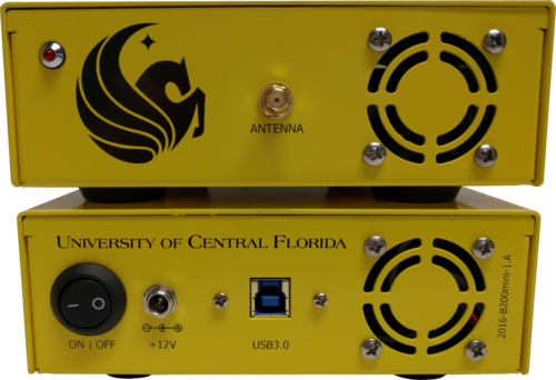 Figure 8: Photograph of the front of the USRP enclosure. A single antenna is switched rapidly between the transmit (TRX) and receive (RX2) ports. The rear panel has ports for power and data (USB3.0). The dimensions of the system are 18x15x5cm (7x6x2in.) and has a mass of approximately 630g (1.4lbs.).
Wireless Temperature Measurements with the USRP
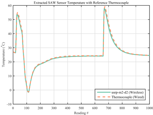
The SAW sensor was interrogated by the USRP and the received signal was post-processed to extract the sensor temperature. A matched filter correlator, previously developed at UCF in MATLAB, has been ported to Python to be compatible with the USRP and Linux. A reference thermocouple (wired) is attached to the SAW sensor (wireless) to ensure that the extracted temperature is accurate. Receiving one data sweep, post processing with 10,000 matched filters, and extracting temperature takes approximately 0.1 seconds. Averaging multiple data sweeps is possible (coherent integration) with 1000 averages taking approximately 1.0 second. The sensor was cooled (cold nitrogen gas) and heated (electric heat gun) randomly before being allowed to return to room temperature. The extracted temperature for the SAW sensor with reference thermocouple are given in Figure 9.
The system is also capable of interrogating multiple sensors, simultaneously. A set of four (4) SAW sensors were designed which are compatible with the USRP system. Each sensor has a unique OFC set and static time delay to the first reflector (ranging from 2.5 to 5 micro-seconds). Each sensor response is 570ns long and each is comprised of 4 OFC chips. The sensors are interrogated simultaneously by the interrogation pulse from the USRP. Each sensor response is then processed separately to extract the sensor temperature. Two (2) sensors were heated/cooled randomly while the other two (2) sensors were left to remain at room temperature. The extracted temperatures for all four (4) temperature sensors is plotted in Figure 10.
-
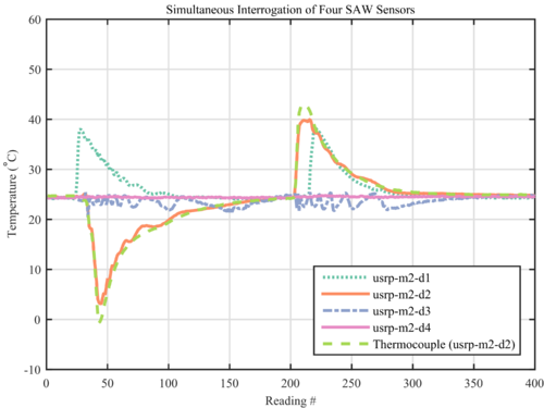 Figure 10: Simultaneous interrogation of four (4) wireless SAW temperature sensors. Two of the sensors were heated (electric heat gun) or cooled (cold nitrogen gas) randomly. The other two sensors were left to remain at room temperature. Some variability in the measurements is evident due to inter-sensor interference.
Conclusion
The USRP B200mini was successfully utilized to implement an efficient interrogation system for passive, wireless SAW strain sensors. A pulsed interrogator design was able to be implemented due to the open-source FPGA design, allowing the custom functionality required by this application to be implemented. The USRP can be quickly reconfigured as the sensor designs evolve to improve performance or for new sensor designs such as strain or gas measurements. Currently, the system is capable of extracting the SAW sensor temperature accurately from a range of up to 5 meters. Work is continuing to improve the system performance as well as implementing different interrogator embodiments.
References
- Malocha, D.C.; Puccio, D.; Gallagher, D., "Orthogonal frequency coding for SAW device applications," Ultrasonics Symposium, 2004 IEEE , vol.2, no., pp.1082,1085 Vol.2, 23-27 Aug. 2004
- Malocha, D.C.; Gallagher, M., "Coherent correlator multi-sensor receiver," Frequency Control Symposium (FCS), 2012 IEEE International , vol., no., pp.1,5, 21-24 May 2012
- Humphries, J.R.; Gallagher, M.W.; Gallagher, D.R.; Weeks, A.R.; Malocha, D.C., "Interrogation of orthogonal frequency coded SAW sensors using the USRP," in Frequency Control Symposium & the European Frequency and Time Forum (FCS), 2015 Joint Conference of the IEEE International , vol., no., pp.530-535, 12-16 April 2015
- Gallagher, M.W.; Smith, W.C.; Malocha, D.C., "An integrated SAW sensor with direct write antenna," in European Frequency and Time Forum & International Frequency Control Symposium (EFTF/IFC), 2013 Joint , vol., no., pp.450-453, 21-25 July 2013
Contact Information
- Dr. Donald C. Malocha
- [email protected]
- University of Central Florida
- CAAT Website

