Direction Finding with the USRP™ X-Series and TwinRX™
Contents
- 1 Application Note Number
- 2 Revision History
- 3 Abstract
- 4 Introduction
- 5 Motivation
- 6 About gr-doa
- 7 Basic Dependencies
- 8 Required Equipment
- 9 What is implemented?
- 10 OSs Tested
- 11 Installation
- 12 Relative Phase Offset Estimation and Correction
- 13 Direction-of-arrival Estimation: An Application
- 14 Conclusion
- 15 Additional Resources and References
Application Note Number
AN-244
Revision History
| Date | Author | Details |
|---|---|---|
| 2016-11-28 | Srikanth Pagadarai Travis Collins Alexander M. Wyglinski |
Initial creation |
Abstract
This application note will cover using the USRP TwinRX™ daughterboard in a direction find application using the MUSIC algorithm.
Introduction
This page will provide detailed instructions for demonstrating the phase synchronization capability of Ettus Research’s TwinRX daughtercards. TwinRX daughtercards can achieve a high degree of accurate phase synchronization except for constant repeatable relative phase offsets. In the following, we will demonstrate a simple method to determine the accuracy of phase synchronization achieved followed by an application of great practical importance in modern wireless communications which fundamentally relies on accurate phase synchronization.
Motivation
Ettus Research provides several convenient solutions for synchronization across multiple USRP (Universal Software Radio Peripheral) devices, which is a critical requirement for certain applications. In addition to these, Ettus Research has introduced the TwinRX daughterboard for USRP X Series radios which is a dual channel superheterodyne receiver that offers a wide dynamic range and accurate phase synchronization except for constant repeatable relative phase offsets. This is achieved by the ability to share the LO between channels across two daughterboards within an X Series radio which enables the phase-aligned operation required to implement four-channel phased arrays. In other words, with a radio configuration consisting of a USRP X300/X310 installed with two TwinRXs, the user has four synchronized receive channels and the need for an OctoClock to distribute 10 MHz and 1 PPS signals is entirely avoided.
About gr-doa
gr-doa is a demonstration on the phase synchronization capability of Ettus Research's TwinRX daughtercards. TwinRX daughtercards can achieve a high degree of accurate phase synchronization except for constant repeatable relative phase offsets. We provide apps to determine the accuracy of phase synchronization achieved and to estimate DoA which fundamentally requires accurate phase synchronization across the receive streams.
Basic Dependencies
- UHD >= 3.10.1.0
- gnuradio >= 3.7.10.1
- armadillo >= 7.300
Dependencies Needed for QA Testing
- octave (Tested 4.0.2)
- octave-signal (Tested 1.3.2)
- scipy (Tested 0.15.1)
- oct2py (Tested 3.5.9)
Dependencies Needed for Documentation
- texlive-latex-base
Required Equipment
- 1 USRP X310 with two TwinRXs installed.
- 1 USRP N210 with an SBX daughtercard (or another USRP/daughtercard of your choice) which will function as a transmitter.
- 9 SMA-M to SMA-M cables. 8 of these need to be of equal length.
- 1 Linear antenna array.
- 1 four-way power splitter (e.g., Mini-Circuits ZFRSC-4-842+).
- 1 30 dB attenuator.
What is implemented?
- A wrapper to the USRP source block when using an X310 with 1 or 2 TwinRXs
- Relative phase offset measurement and correction
- Antenna element calibration for linear arrays
- MUSIC algorithm for linear arrays
- Root-MUSIC algorithm for linear arrays
OSs Tested
- Ubuntu 14.04, Ubuntu 16.04
Installation
    git clone https://github.com/EttusResearch/gr-doa
    cd gr-doa
    mkdir build
    cd build
    cmake ..
    make
    make test
    sudo make install
    sudo ldconfig
Relative Phase Offset Estimation and Correction
A USRP X310 equipped with Twin RX daughtercards is capable of sharing LOs and clock/time references. The first step is to estimate the repeatable constant relative phase-offsets between the four receive channels. For this step, the following is the list of items needed:
- 1 USRP X310 with two TwinRXs installed.
- 1 USRP N210 with an SBX daughtercard (or another USRP/daughtercard of your choice) which will function as a transmitter.
- 5 SMA-M to SMA-M cables. 4 of these need to be of equal length.
- 1 four-way power splitter (e.g., Mini-Circuits ZFRSC-4-842+).
- 1 30 dB attenuator.
Then,
- Connect the RF1 port of USRP N210 via the 30 dB attenuator to the input port of the power splitter using an SMA cable.
- Connect the four output ports of the power splitter to the TX/RX and RX2 ports of RF-A and RF-B on the X310 using 4 equal-length SMA cables.
- In the host PC connected to the transmitter, open
run_DoA_transmitter.grcingr-doa/apps. Provide values for tone frequency, sample rate and center frequency. Provide the IP address of the radio. Execute the flowgraph. - In the host PC connected to the receiver, open
estimate_X310_TwinRX_constant_phase_offsets_and_save.grcingr-doa/apps. Ensure that tone frequency, sample rate and center frequency are the same as those at the transmitter. Configure the IP address of the radio and the path where the config file containing phase offset values will be stored. Execute the flowgraph. - In the host PC connected to the receiver, open
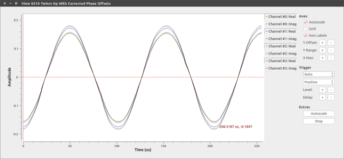
view_X310_TwinRX_op_with_corrected_phase_offsets.grcingr-doa/apps. Ensure that parameters such as sample rate, tone frequency, gain etc. are the same values asestimate_X310_TwinRX_constant_phase_offsets_and_save.grc. Run the flowgraph and verify that the phases offsets are corrected. - Open
calculate_X310_TwinRX_phase_sync_accuracy.grcingr-doa/apps. Ensure that parameters such as sample rate, tone frequency, gain etc. are the same values asestimate_X310_TwinRX_constant_phase_offsets_and_save.grc. Configure the path where the config file containing corrected phase offset values will be stored. Run the flowgraph and open the config file to determine the accuracy of phase offset correction.
Figure 1: Viewing the TwinRX's received streams with corrected phase offsets.
The USRP X310 equipped with two TwinRXs is now calibrated and ready for use. It can now receive signals to be processed by any array signal processing application that requires accurate phase synchronization between receive channels. To demonstrate this feature, we will show two direction-of-arrival (DoA) estimation algorithms in action.
Direction-of-arrival Estimation: An Application
Multiple Signal Classification (MUSIC) was one of the earliest algorithms developed for DoA estimation. It requires that the following assumptions are satisfied:
- the received waveform is narrowband,
- the received waveform consists of D plane-wave signals plus uncorrelated noise,
- the number of plane-wave signals, D is known,
- the number of antenna elements, N is at least equal to D+1 and
- the inputs received across the antenna array for the purpose of DoA estimation are phase-synchronous.
MUSIC processes the sample correlation matrix constructed using samples received by an antenna array, determines the noise subspace of the matrix and estimates the DoA of a target to be the arg-max. of a pseudo-spectrum. Root-MUSIC, which is a variant of MUSIC algorithm estimates the DoA of a target to be a root of a polynomial function constructed using the correlation matrix and satisfies certain criteria.
The modules that implement MUSIC and Root-MUSIC algorithm utilize the relative phase offsets computed in the previous step. They are developed using GNU Radio framework. For a simulation example that demonstrates the application of MUSIC algorithm, please see gr-doa/apps/run_MUSIC_simulation.grc. For a simulation example that demonstrates the application of Root-MUSIC algorithm, please see gr-doa/apps/run_RootMUSIC_simulation.grc.
The detailed list of steps for MUSIC and Root-MUSIC demonstration using Ettus Research USRP X310 with two TwinRX daughtercards, is shown below. In addition to the list of items indicated in the previous step, we also require:
- 5 Vert2450 antennas (or other antennas of your choice which have a good gain-phase relationship in your frequency band of choice).
- (Optional) An array fixture with variable antenna element separation distances and 4 equal length SMA-M to SMA-M cables to connect the antennas held in place by the array fixture to the TX/RX and RX2 ports of RF-A and RF-B on the X310.
IMPORTANT: It is strongly recommended that the antenna element separation is half-wavelength or lower depending on the tone center-frequency. Arranging antenna elements at larger distances leads to an aliasing effect and compromises the angle resolution capability of the DoA algorithms. The detailed list of steps for DoA demonstration are as follows:
- Disconnect the cables connecting the transmitter and the receiver. Position the transmitter at a distance from the receiver antenna array and at a known angle.
- In the host PC connected to the transmitter, open
run_DoA_transmitter.grcingr-doa/apps. Provide values for tone frequency, sample rate and center frequency. Provide the IP address of the radio. Execute the flowgraph.
- In the host PC connected to the receiver, open
calibrate_lin_array_X310_TwinRX.grc. If your array geometry is rectangular, open the corresponding flowgraph. Configure the flowgraph settings by providing the pilot target's DoA, the radio's ip-address etc. ininput_variables. Select the path and config filename where the antenna array calibration coefficients will be stored. Execute the flowgraph.
- Now, change the position of the transmitter and note the geometrical angle that is to be expected.
- In the host PC connected to the receiver, open
run_MUSIC_lin_array_X310_TwinRX.grcingr-doa/apps. Configure the flowgraph settings by providing additional parameters toinput_variables. Please see the documentation tab of the blocks for more information on the arguments needed. Execute the flowgraph.
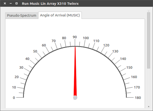
- Verify that the angle of arrival as shown by the Compass widget matches the expected angle. When conducting this experiment with a linear array, note that the visibility region is 0 to 180 degrees.
Figure 2: Compass widget showing a source at 90° to the linear array.
Conclusion
This page summarized the step-by-step process involved in calibrating a USRP X310 with two TwinRXs for constant relative phase offsets using the GNU Radio flowgraphs provided. As a follow-up, detailed steps for direction of arrival estimation, an application that fundamentally depends on accurate phase offset calibration across the receive streams have been provided.
Additional Resources and References
- Synchronization and MIMO Capability with USRP Devices - https://kb.ettus.com/Synchronization_and_MIMO_Capability_with_USRP_Devices
- For a concise description of the steps involved:
https://github.com/EttusResearch/gr-doa/wiki - For details about the blocks available in this package:
gr-doa/build/docs/doxygen/html/index.html - For detailed description:
gr-doa/docs/whitepaper/doa_whitepaper.pdf


