RFNoC (UHD 3.0)
Contents
Overview
Framework and Data Flow Example
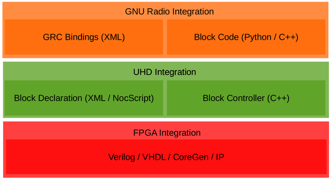
Below is a figure of the RFNoC stack.
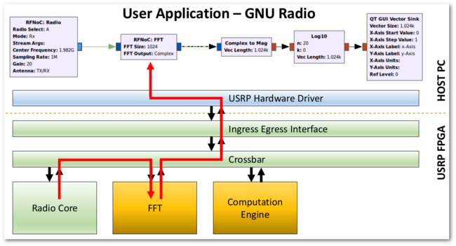
The example below shows basic data flow of an RFNoC application. While this shows one possible data flow, there are many possible combinations from Host block to FPGA block, FPGA block to Host block, Host to Host, FPGA to FPGA, etc.
Supported Devices
- E310/E312
- X300/X310
Sample of Available Blocks
- FIFO
- FFT
- FIR
- fosphor (real-time spectrum analyzer)
- Decimator (Keep 1 in N)
- Log Power Calculator
- Radio Interface
- Vector IIR (moving average)
- Window multiplier (for FFT)
- OFDM: Burst detection + synchronization, equalizer, packet demodulator
- and more...
Blocks Included with Default FPGA Images
The following images have the corresponding RFNoC blocks (Computation Engines):
| Image Name | Included Blocks |
|---|---|
usrp_x300_fpga_HG.bit
|
2x DDC, 2x DUC
|
usrp_x300_fpga_RFNOC_HG.bit
|
DUC, DDC (one channel), fosphor, window, fft, 2x AXI FIFOs
|
usrp_x310_fpga_RFNOC_HG.bit
|
DUC, DDC (one channel), fosphor, window, fft, 2x AXI FIFOs, Keep One in N, FIR, Siggen
|
usrp_e310_fpga.bit
|
1x DDC, 1x DUC
|
usrp_e310_fpga_RFNOC.bit (sg1 version)
|
fosphor, window, fft, 2x AXI FIFOs, FIR
|
RFNoC FAQs
FPGA
What is the purpose of the rb_stb signal on NoC Shell?
When writing or reading a settings register in a RFNoC block, the block receives a command packet (with the register address / value to write as the payload) and sends out a response packet. The response packet acknowledges the command packet and includes readback data as the payload. In the write case, the readback data is usually discarded. In the read case, the readback data payload will be the value of the register read in the block.
The signal rb_stb, called readback strobe, is used to control the the output of the response packet. After receiving a command packet, Noc Shell’s command packet processor will not output a response packet unless rb_stb is asserted. This functionality can be used to throttle the reception of command packets / settings register read/writes.
Most blocks should keep rb_stb asserted. Note, the rb_stb bit width is as wide as the number of block ports in use. For example, a two block port RFNoC block should set rb_stb to 2’b11, otherwise a command packet timeout will occur.
UHD
Why do I have a command timeout error?
Error message example:
RuntimeError: EnvironmentError: IOError: 0/FIR_0 user_reg_read64() failed: EnvironmentError: IOError: [0/FIR_0] sr_read64() failed: EnvironmentError: IOError: Block ctrl (CE_04_Port_70) no response packet - AssertionError: bool(buff)
in uint64_t ctrl_iface_impl::wait_for_ack(bool)
at /home/ettus/src/uhd/host/lib/rfnoc/ctrl_iface.cpp:205
- Check
ce_clk/ce_rstare correctly connected inrfnoc_ce_auto_inst_<device>.vfile where<device>isx300,x310, ore310. - Check block is correctly connected to the crossbar. Generally this is only an issue if manually connecting RFNoC block’s signals to the crossbar.
- Check if Noc Shell’s
rb_stbsignal is properly asserted. Note,rb_stbbit width must be as wide as the number of block ports in use, i.e. if using 2 block ports,rb_stbmust be2’b11. - RFNoC block is using timed commands (
USE_TIMED_CMDS) with Noc Shell and the command FIFO depth parameter (CMD_FIFO_SIZE) on Noc Shell is too small. UHD will issue up to 64 commands at once, so setCMD_FIFO_SIZEto at least8.
GNU Radio
When do I use an RFNoC FIFO in my flowgraph and which kind if any?
An RFNoC FIFO is needed in your flowgraph in the following 2 conditions:
First, if you are running a GNU Radio flowgraph that is structured as follows:
Host block -> RFNoC block -> Host block
In this case, you need to do either:
Host block -> RFNoC FIFO -> RFNoC Block -> Host block
-OR-
Host block -> RFNoC Block -> RFNoC FIFO -> Host block
The order doesn't matter. This structure also benefits from having the GNU Radio Throttle block in the sequence. The reason behind the need to add the FIFO is because of performance inside of GNU Radio, so that the RX/TX work functions in the GNU Radio RFNoC block implementations run in separate threads.
Use RFNoC: FIFO (AXI_FIFO_LOOPBACK) in this case. See the following figure as an example.
Second, in the case where you are transmitting out to the antenna on the X3xx series devices, i.e.
Host -> DmaFIFO -> Radio
-OR-
Host -> DmaFIFO -> DUC -> Radio
Ethernet introduces a latency in flow control from the X3x0 back to the host. The latency will cause underruns unless a large buffer, i.e. DMA_FIFO, is added to the flowgraph.
Use RFNoC: DmaFIFO (AXI_DMA_FIFO) in this case. See the following figures as examples.
-OR-
Splitting an RFNoC Data Stream in GNU Radio
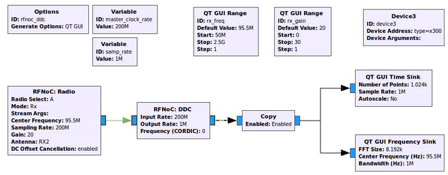
Copy Block: In the RFNoC domain, streams of data can not be split as easily as they are in the GNU Radio domain. The Copy block depicted in the screenshot below serves the function as a stream splitter at the FPGA-Host boundary. It’s main purpose, when Enabled, is to copy the samples it is getting at its input and putting then into the output, but here it is also serving as a boundary between a RFNoC-domain and a GNURadio-domain. In the flowgraph above. after this boundary is passed, the data stream can easily be split into the two sinks to have them run simultaneously (standard GNU Radio functionality). It is possible to connect the GNU Radio blocks directly to RFNoC blocks without a Copy block, but only one would work at a time (the other ones would have to be disabled). Another way to split data streams from the RFNoC-domain is to use the RFNoC: Split Stream block, which would split the streams in the RFNoC domain, but this is not very useful here as we are moving into the GNURadio-domain.
What is the difference between USRP Sink/Source blocks and the RFNoC:Radio block?
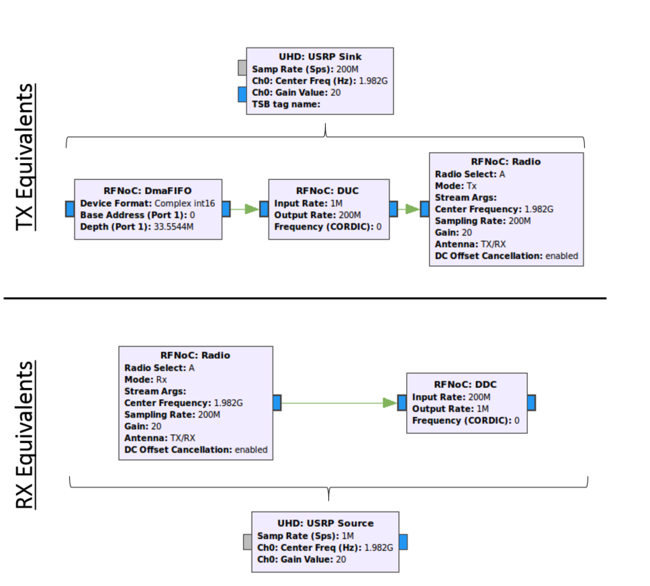
The USRP Source and Sink blocks use the multi_usrp API, whereas the RFNoC:Radio block uses the RFNoC API. In general, unless RFNoC features are desired, there is no need to use the RFNoC:Radio block. The RFNoC:Radio block is most useful when its output is connected directly to another RFNoC block. Below is a list of differences as well as a GRC screenshot to help differentiate between the two blocks.
Distinctions:
- The USRP Source/Sink blocks work with any version of UHD, and does not require
gr-ettus. Thegr-ettusOut-Of-Tree GNU Radio module is currently needed to use any RFNoC Blocks. This requirement will be removed as more RFNoC components are migrated into UHD. - The USRP Source/Sink blocks include a superset of the not only the components of an
RFNoC:Radio, but alsoDDC/DUCchains, and theDRAM FIFO(specific to X3xx series). When using theRFNoC:Radioblock, theDDC/DUCblocks need to be added explicitly. See the figure below. - When using the USRP Source/Sink blocks, it is not possible to connect to any RFNoC blocks.
- USRP Source/Sink blocks can only be used when using a
multi_usrpAPI FPGA image (when looking in the USRP FPGA images directory they are the images without the term “RFNOC” in them), or an FPGA image that includesRFNoC:RadioandRFNoC:DDC/DUCblocks.
NOTE: The RFNOC:DmaFIFO block is only needed for the X3xx series devices.
Tools
Xilinx License: Xilinx’s License manager looks for an Ethernet adapter with the name eth0...
Problem: The Xilinx Vivado License Manager looks for an Ethernet adapter with the name eth0, but Ubuntu 16.04 and later now use a persistent naming scheme, with interface names such as (e.g. np6s0, enp4s0, enp2s0f0, enp2s0f1, enx00ef5c620935).
Solution: Rename the ethernet adapter to eth0.
Create this file:
70-persistent-net.rules in this /etc/udev/rules.d/ directory
And adding the following line to the file (substitute xx:xx:xx:xx:xx:xx for the MAC address of the Ethernet adapter):
SUBSYSTEM=="net", ACTION=="add", DRIVERS=="?*", ATTR{address}=="xx:xx:xx:xx:xx:xx", ATTR{dev_id}=="0x0", ATTR{type}=="1", NAME="eth0"
Ubuntu information:
http://askubuntu.com/questions/767786/changing-network-interfaces-name-ubuntu-16-04
Xilinx information:
https://www.xilinx.com/support/answers/60510.html

