OAI Reference Architecture for 5G and 6G Research with USRP
Contents
- 1 Authors
- 2 Application Note Number
- 3 Abstract
- 4 NI Part Numbers
- 5 Overview of the USRP N300 and N310
- 6 Overview of the USRP N320 and N321
- 7 Overview of the USRP X410
- 8 Overview of the OpenAirInterface (OAI) Software Stack
- 9 Overview of the Reference Architecture
- 10 Bill of Materials (BoM)
- 11 Hardware Requirements
- 12 Software Requirements
- 13 Installing and Configuring the UHD Software
- 14 Installing and Configuring the USRP Radio
- 15 Configuring the Ubuntu Linux Operating System
- 16 Configuring the BIOS for gNB and UE Systems
- 17 Installing, Configuring, and Running the CN System
- 17.1 Prerequisites for the Scenario 1 Minimalist Deployment
- 17.2 Pull Base Images
- 17.3 Pulling the images from Docker Hub
- 17.4 Synchronizing the installed images
- 17.5 Configure the Containers
- 17.6 Deploy the containers
- 17.7 Installing docker-compose and Wireshark
- 17.8 Invoking the Core Network
- 17.9 Stopping the Core Network
- 18 Installing, Configuring, and Running the gNB System
- 18.1 Building and installing the gNB software
- 18.2 Editing the gNB configuration file
- 18.3 Specifying the AMF IP address
- 18.4 Specifying the gNB IP address
- 18.5 Specifying the USRP IP address
- 18.6 Adding a static route to the CN system
- 18.7 Invoking the gNB
- 18.8 Interfaces Between gNB and Core Network
- 18.9 Testing Connectivity Between gNB and CN
- 19 Installing, Configuring, and Running the UE System
- 20 End-to-End Verification
- 21 Technical Support
Authors
Neel Pandeya, Bharat Agarwal, Gerardo Trevino
Application Note Number
AN-956
Abstract
This Application Note presents a reference design for using the Eurecom OpenAirInterface (OAI) software stack to implement 5G NR Stand-Alone (SA) systems on the USRP N300, N310, N320, N321, X410 radio devices. The reference design covers the base station (gNB), the user equipment (UE), and the Core Network (CN) components of the network. Three types of UE are used: a UE running on a USRP radio; a wireless modem module UE; and a commercial (COTS) handset/phone. The reference design supports operation in Frequency Range 1 (FR1), and support for operation in FR2 will be added at a future date. The various aspects of installing, configuring, and running the hardware and software components of the network are discussed in detail, along with a discussion of expected results, methods to benchmark and monitor the system, and troubleshooting steps.
The solution brochure for the OAI Reference Architecture for 5G and 6G Research with the USRP can be downloaded here.
An overview of using OAI Software for 5G and 6G research at this webpage here.
You can learn more about other solutions for 5G and 6G Wireless Research and Prototyping at the webpage here.
NI Part Numbers
The table listed below shows the contents of several pre-configured bundles for the OAI USRP Reference Architecture, which can be ordered using the corresponding NI part number. For more information about these bundles, please contact us at [email protected].
| P/N | System Name | Description |
|---|---|---|
| 868063-01 | USRP X410 OAI Bundle For 5G and 6G Research Base | Ettus USRP X410 (4 TX and 4 RX, 400 MHZ BW, 1 MHz to 7.2 GHz SDR, GPSDO) |
| 868063-02 | USRP X410 OAI Bundle For 5G and 6G Research Standard | Example |
| 868063-03 | USRP N310 OAI Bundle For 5G and 6G Research Base | Example |
| 868063-04 | USRP N310 OAI Bundle For 5G and 6G Research Standard | Example |
| 868063-05 | USRP N321 OAI Bundle For 5G and 6G Research Base | Example |
| 868063-06 | USRP N320 OAI Bundle For 5G and 6G Research Base | Example |
Overview of the USRP N300 and N310
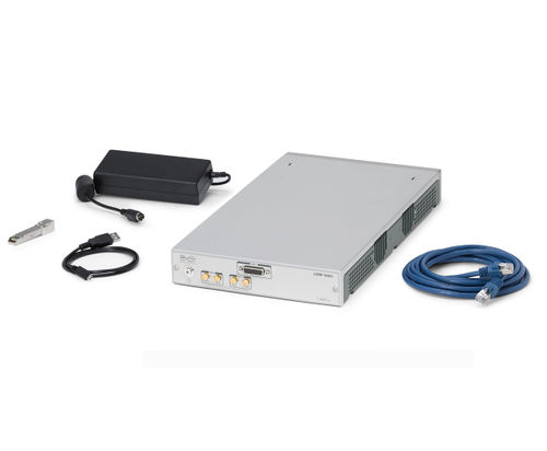
The USRP N300 and N310 are a networked software defined radio that provides reliability and fault-tolerance for deployment in large scale and distributed wireless systems. This device simplifies control and management of a network of radios by introducing the unique capability to remotely perform tasks such as debugging, updating software, rebooting, factory resetting, self-testing, and monitoring system health. The USRP N310 is an all-in-one device that includes two AD9371 transceivers, the Zynq-7100 SoC baseband processor, two SFP+ ports, a built-in GPSDO module, and various other peripheral and synchronization features.
The N300 features:
|
The N310 features:
For more detailed technical information about the USRP N300 and N310, please reference the N300/N310 Hardware Resource Page. For more information about getting started with the USRP N300 and N310, please reference the Getting Started Guide. |
Overview of the USRP N320 and N321
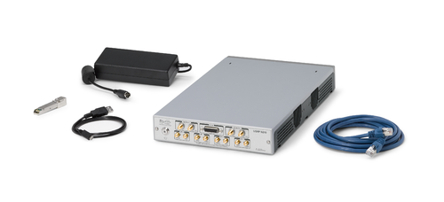
The USRP N320 and N321 are a networked software defined radio that provides reliability and fault-tolerance for deployment in large scale and distributed wireless systems. This is a high performance SDR that uses a unique RF design by Ettus Research to provide 2 RX and 2 TX channels in a half-wide RU form factor. Each channel provides up to 200 MHz of instantaneous bandwidth, and covers a frequency range from 3 MHz to 6 GHz. The baseband processor uses the Xilinx Zynq-7100 SoC to deliver a large user programmable FPGA for real-time, low latency processing and a dual-core ARM CPU for stand-alone operation.Support for 1 GbE, 10 GbE, and Aurora interfaces over two SFP+ ports and 1 QSFP+ port enables high throughput IQ streaming to a host PC or FPGA coprocessor. A flexible synchronization architecture with support for LO sharing for TX and RX, 10 MHz clock reference, PPS time reference, GPSDO, and White Rabbit enables implementation of phase coherent MIMO testbeds. The USRP N320 leverages recent software developments in UHD to simplify control and management of multiple devices over the network with the unique capability to remotely administrate tasks such as debugging, updating software, rebooting, resetting to factory state, and monitoring system health.
The USRP N320 features:
|
The USRP N321 features:
For more detailed technical information about the USRP N320 and N321, please reference the N320/N321 Hardware Resource Page. For more information about getting started with the USRP N320 and N321, please reference the Getting Started Guide. |
|
Overview of the USRP X410
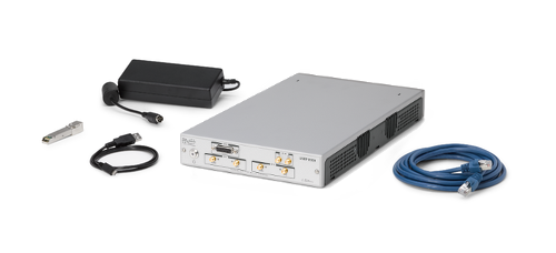
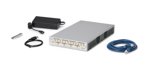
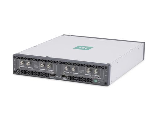
The USRP X410 is a high-performance, multi-channel software defined radio. The SDR is designed for frequencies from 1 MHz to 7.2 GHz, tunable up to 8 GHz and features a two-stage superheterodyne architecture with 4 independent TX and RX channels capable of 400 MHz of instantaneous bandwidth each. Digital interfaces for data offload and control include two QSFP28 interfaces capable of 100 GbE[1], a PCIe Gen3 x8 [3] interface, as well standard command, control, and debug interfaces: USB-C JTAG, USB-C console, Ethernet 10/100/1000. The USRP X410 is an all-in-one device built on the Xilinx Zynq Ultrascale+ ZU28DR RF System on Chip (RFSoC) with built-in digital up and down conversion and onboard Soft-Decision Forward Error Correction (SD-FEC) IP.
The USRP X410 features:
For more detailed technical information about the USRP X410, please reference the X410 Hardware Resource Page. For more information about getting started with the USRP X410, please reference the X410 Getting Started Guide. |
|
Overview of the OpenAirInterface (OAI) Software Stack
The OpenAirInterface (OAI) software provides an open-source, standards-compliant implementation of a 3GPP 5G NR stack that runs on a commodity x86 CPU and a USRP radio device. OAI was initially developed by Eurecom, which is a university in France. It is now managed and developed by the OpenAirInterface Software Alliance (OSA), which is a French non-profit organization that provides open-source software and tools for 4G and 5G wireless research. Further information can be found on the Eurecom website.
The OAI software provides a 5G NR implementation that runs in real-time and is capable of operating with commercial 5G NR handsets (UEs). The OAI software includes implementations of the gNB, the UE, and the Core Network (CN). Further information can be found on the OAI website and their GitLab repository, listed below.
The availability of OAI source code is free for non-commercial and academic research purposes. More information about licensing can be found on the OAI website at here and here.
Overview of the Reference Architecture
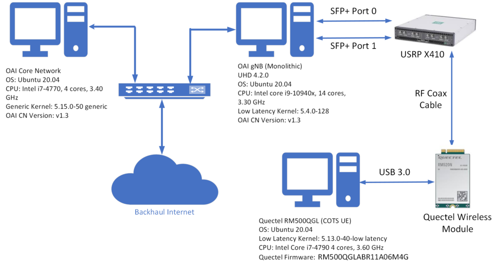
The diagram below shows the layout and architecture of this 5G OAI USRP reference architecture.
The diagram below shows the RF cable connections between the USRP X410 and the Quectel wireless modem module.
The diagram below shows the software layout and architecture across the Core Network, gNodeB, and UE systems.
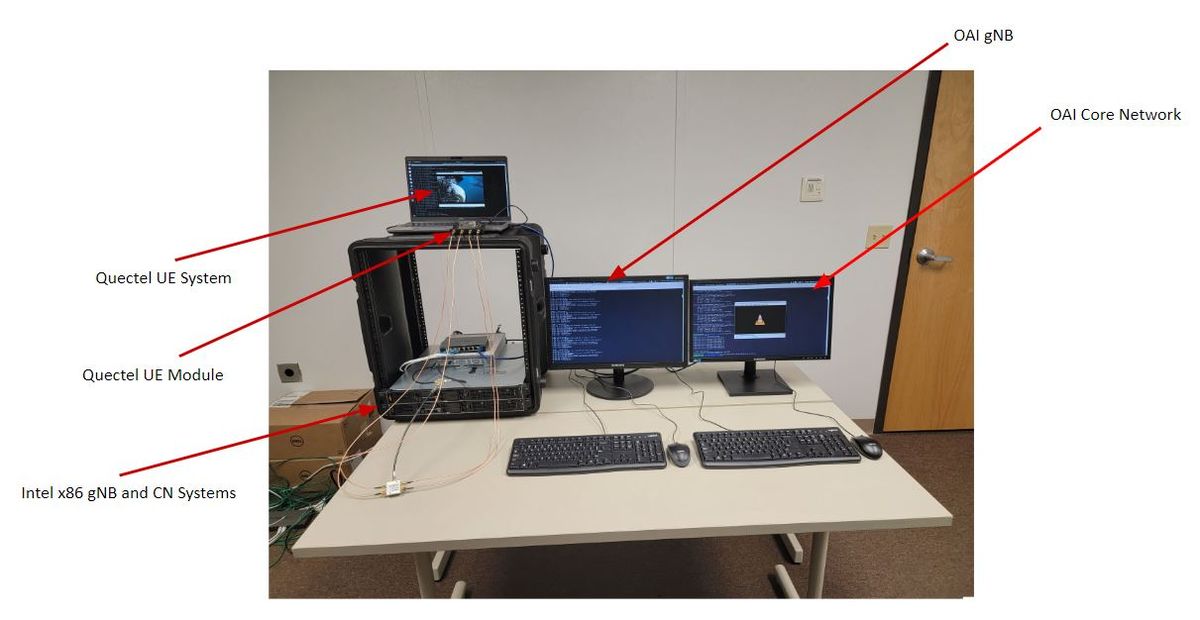
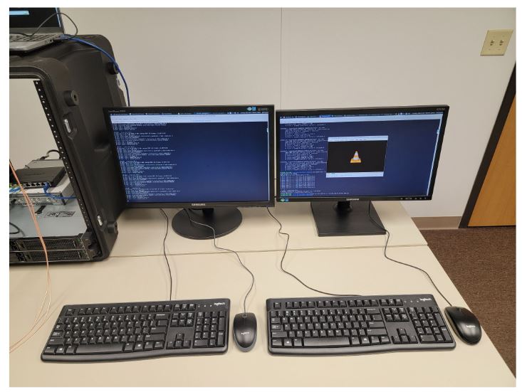
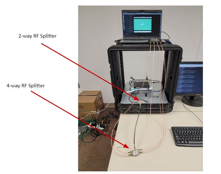
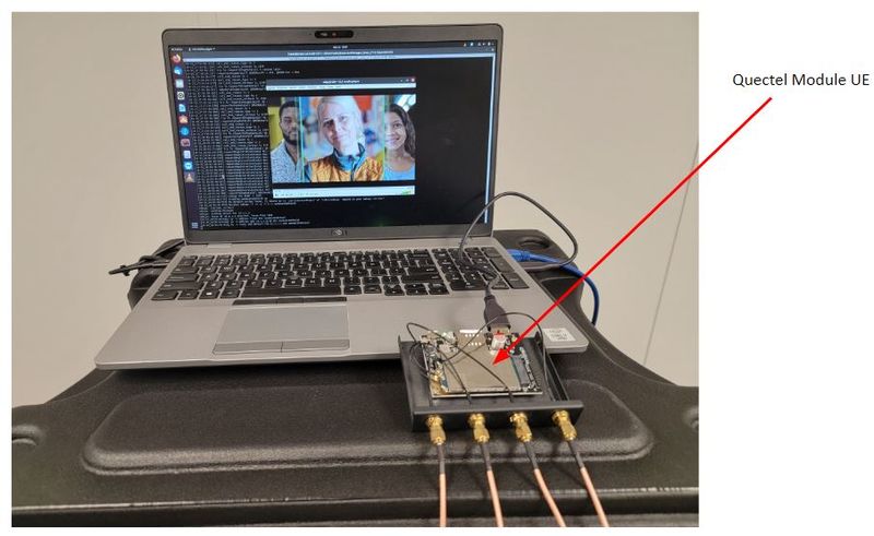
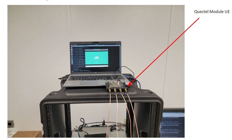
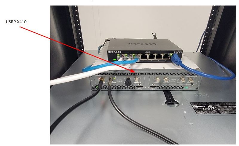
The photos below show one physical implementation of the reference architecture in the office of the authors. Note that this is not the sole valid system implementation, but it is one of many possible valid system implementations.
Bill of Materials (BoM)
The full Bill of Materials (BoM) for the reference design is listed below. The BoM includes all the hardware components for the multiple system configuration scenarios, where the USRP N300, N310, N320, N321, X410 can be used for the gNB and the UE system, and the UE itself can be implemented with a USRP device, or with a wireless modem module, or with a COTS handset.
- Three desktop computers, with Intel Core i9 CPU, of 10th, 11th, or 12th Generation, with clock speed of minimum 4.0 GHz, with minimum 10 physical cores, and also with only NVMe disk drives. See further details about this item in the Hardware Requirements section.
- Two 10 Gbps Ethernet networks cards. We recommend the Intel X710-DA2 and the Nvidia/Mellanox MCX4121A-ACAT ConnectX-4 network cards. See further details about this item in the Hardware Requirements section.
- Two USRP devices. The USRP may be any of USRP N300, N310, N320, N321, X410. There will be one USRP for the gNB, and one USRP for the UE. The USRP devices can be mixed (i.e., the gNB could run with a USRP X410, while the UE runs with a USRP N310).
- https://kb.ettus.com/N300/N310
- https://kb.ettus.com/N320/N321
- https://kb.ettus.com/X410
- https://www.ettus.com/all-products/usrp-n300/
- https://www.ettus.com/all-products/usrp-n310/
- https://www.ettus.com/all-products/usrp-n320/
- https://www.ettus.com/all-products/usrp-n321/
- https://www.ettus.com/all-products/usrp-x410/
- One QSFP28-to-SFP28 breakout cable (NVIDIA MCP7F00-A003R26N DAC Splitter Cable Ethernet 100GbE to 4x25GbE 3m). This is only needed when using the USRP X410.
- https://store.mellanox.com/products/nvidia-mcp7f00-a003r26n-passive-copper-splitter-cable-ethernet-100gbe-to-4x25gbe-qsfp28-to-4xsfp28-3m-colored-26awg-ca-n.html
- https://store.mellanox.com/products/nvidia-mcp7f00-a003r30l-passive-copper-splitter-cable-ethernet-100gbe-to-4x25gbe-qsfp28-to-4xsfp28-3m-colored-30awg-ca-l.html
- One OctoClock-G. This is needed to synchronize the gNB USRP and the UE USRP. Ensure that device used is the "-G" model, which contains an internal GPSDO module. This is only needed when the UE is implemented on a USRP device.
- Four 10 Gbps Ethernet cables with SFP+ terminations. These cables are available in 0.5, 1.0, and 3.0 meter lengths. These cables are needed when using the USRP N300, N310, N320, N321, but not when using the USRP X410.
- Four VERT900 antennas and/or four VERT2450 antennas. You can use either of these antennas based on the bands in use. There are also many third-party vendors selling a wide variety of antennas, such as omnidirectional antennas. As long as the antenna has an 50-ohm impedance and has SMA connectors, then it can be used with the USRP radio.
- One Quectel RM500Q-GL 5G wireless modem module. See further details about this item in the Hardware Requirements section.
- One Google Pixel 5A 5G handset (phone). Be sure that the handset is unlocked.
- Two 5G SIM cards and one USB UICC/SIM card reader/writer.
- One Mini-Circuits 4-way DC-Pass, SMA, Power Splitter, 250 to 6000 MHz, 50Ω (ZN4PD1-63HP-S+).
- Two Mini-Circuits, 2-way, DC-Pass SMA, Power Splitter, 500 to 5000 MHz, 50Ω (ZN2PD2-50-S+).
- Four Mini-Circuits, VAT-10+, 10 dB Fixed Attenuator, DC to 6000 MHz, 50Ω, SMA.
- Four Mini-Circuits, VAT-20+, 20 dB Fixed Attenuator, DC to 6000 MHz, 50Ω, SMA.
- Four Mini-Circuits, VAT-30+, 30 dB Fixed Attenuator, DC to 6000 MHz, 50Ω, SMA.
- Fourteen Coax SMA Cables, Mini-Circuits, SMA, Hand-Flex Interconnect, 18.0 GHz, 36 inches length (086-36SM+).
- One NETGEAR GS108 8-Port Gigabit Ethernet Unmanaged Switch. See further details about this item in the Hardware Requirements section.
- Three adapters from USB 3.0 to 1 Gbps Ethernet. Any major reputable brand will work. Use either USB-A or USB-C connector as per the ports available on your host computer.
Hardware Requirements
Host Computers
Three host computers are needed, one for the gNB, one for the UE, and one for the CN, with the specifications discussed in this section. The requirements for the host computer running the CN are not as high as for the gNB and UE, but we recommend that all three host computers meet the requirements described here. We also strongly recommend that each of the gNB, UE, and CN be implemented on their own dedicated system. A single host computer should only run the gNB, or the UE, or the CN.
CPU
We recommend using an Intel Core i9 CPU, or an Intel Xeon CPU, 10th, 11th, or 12th Generation, with minimum clock speed of 4.0 GHz, and with minimum 10 physical cores. Examples of such a CPU would be the Intel i9-10940X CPU, which has 14 physical cores, 4.60 GHz clock speed, and is 10th generation, and the Intel i9-12900K CPU, which has 16 physical cores, 5.20 GHz clock speed, and is 12th generation, as well as the Intel Xeon Platinum 8351N. Be sure that the CPU has at least 40 PCIe lanes, or at least enough lanes to support any GPU and 10 Gbps Ethernet card that are being used. The system should ideally support PCIe Gen 4.
Disk
We strongly recommend that only NVMe SSD disks are used. Many systems now use PCIe Gen-4, and we recommend using a PCIe Gen-4 NVMe SSD disk. We recommend the Samsung 980 PRO SSD drive. Do not SATA disks at all. Using a RAID configuration with multiple drives should not be necessary, although this can potentially be an option for further increasing performance and throughput.
Memory
The system should have either dual-channel or quad-channel DDR4 or DDR5 (preferred) memory, with the highest clock speed available. A minimum of 16 GB or 32 GB of memory should be sufficient. Larger amounts of memory should not be necessary, as no virtualization, RAM disk, or other large in-memory buffering is being used.
GPU
The GPU does not matter for the purposes of running UHD and OAI. If you might be doing some AI/ML processing in then GPU, then you may want to use a particular GPU. The OAI 5G stack does not currently leverage the GPU.
10 Gbps Ethernet network card
The gNB and UE system will need a two-port 10 Gbps Ethernet network card for connecting to the USRP radio. The CN system does not connect to any USRP, so it does not need a 10 Gbps Ethernet network card.
There are several cards that are relevant and that we recommend, depending on the specific use-case.
The Intel X710-DA2 is a solid network card, and works out-of-the-box with Ubuntu 20.04.4. However, it has some issues with DPDK. This reference design is not initially using DPDK, so these issues are not yet relevant. The card is widely availabe and relatively inexpensive. The X710-DA4 is a four-port version of the card.
Be sure that the computer's chassis can physically accommodate the network card.
The Mellanox MCX4121A-ACAT ConnectX-4 is also a solid network card, and also works out-of-the-box with Ubuntu 20.04.4. Furthermore, it works well with DPDK.
QSFP28-to-SFP28 Breakout Cable for USRP X410
The USRP X410 only has a QSFP28 port, which is for 100 Gbps Ethernet. In order to connect the USRP X410 to the host computer via 10 Gbps Ethernet, a QSFP28-to-SFP28 breakout cable is needed. This cable will be required when using the USRP X410, and will connect directly to the 10 Gbps Ethernet cards. This cable is not needed for the USRP N300, N310, N320, N321.
It is certainly possible to directly connect the host computer to the 100 Gbps QSFP28 port of the USRP X410. In order to do this, a QSFP28 100 Gbps Ethernet card would be needed. We recommend the Mellanox/Nvidia MCX516A-CCAT (PCIe Gen3), and the Mellanox/Nvidia MCX516A-CDAT (PCIe Gen4). You will also need a QSFP28 cable. We recommend the Mellanox/Nvidia MCP1600-C003E26N, and the Mellanox/Nvidia MCP1600-C003E30L and MCP7F00-A001R30N. We also recommend the Intel E810 series network cards. There are both 100 Gbps Ethernet QSFP28 cards and 10 Gbps Ethernet SFP28/SFP+ cards. All these cards work well with Ubuntu 20.04 and DPDK.
However, in this release of the reference design, it is not necessary to use 100 Gbps Ethernet, which is only needed for supporting high aggregate data rates, such as for the larger 200 MHz and 400 MHz FR2 channel bandwidths, and/or for 2x2 MIMO configuration, both of which are not yet supported. For this release of the reference design, we recommend using the Intel X710-DA2 and the Mellanox MCX4121A-ACAT ConnectX-4 cards, and using dual 10 Gbps Ethernet connections.
Example Systems
There are many vendors who sell host computers that meet these requirements. This reference design was implemented using System 76 Thelio Mira systems and Dell Precision 5820 systems. Both systems have flexible configuration options, and can be configured as described in this section.
USRP Devices
Two USRP devices are needed, one for the gNB, and one for the UE. The USRP may be any of USRP N300, N310, N320, N321, X410. The USRP devices can be mixed (i.e., the gNB could be implemented with a USRP X410, while the UE could be implemented with a USRP N310). All these USRP devices can support all the channel bandwidths in FR1, up to and including 100 MHz. For FR2, the USRP N320 can support the 50, 100, 200 MHz channel bandwidths, and the USRP X410 can support all the 50, 100, 200, 400 MHz channel bandwidths.
OctoClock-G
One OctoClock-G device is needed to synchronize the gNB USRP and the UE USRP. Ensure that device used is the "-G" version of the OctoClock, which contains an internal GPSDO module. This is only needed when the UE is implemented on a USRP device.
Host Computer for 5G Wireless Modem Module
One implementation of the UE is a 5G wireless modem module, such as the Quectel RM500Q-GL. The modem module requires a device driver and a connection to a host computer. It is possible to use one of the gNB, UE, CN host computers to also drive the modem module, but it is recommended to have a separate dedicated fourth host computer for this. This host computer need not be powerful or high-performance, and may run either Ubuntu 20.04 or Windows 10. It may be preferred to use Windows 10, as the Qualcomm drivers may work better on Windows than on Linux.
Software Requirements
Operating System
The required operating system for the gNB, UE, CN systems is Ubuntu 20.04.4. Be sure to use the Desktop image, not the Server image. It is also necessary to use the low-latency kernel on the gNB and UE systems, but not on the CN system. The kernel version should be 5.15 for Ubuntu 20.04.4. The "Installing and Configuring the UHD Software" section contains detailed information about what specific package dependencies need to be installed, and how to install the low-latency kernel. Either Kubuntu or Xubuntu may also be used, instead of Ubuntu. Do not run Ubuntu in a Virtual Machine (VM). Do not use any virtualization. Be sure to install Ubuntu on-the-metal.
The reference architecture will add support for Ubuntu 22.04.1 in the near future.
- https://releases.ubuntu.com/20.04/
- https://xubuntu.org/download/
- https://kubuntu.org/getkubuntu/
- https://en.wikipedia.org/wiki/Ubuntu
- https://en.wikipedia.org/wiki/Xubuntu
- https://en.wikipedia.org/wiki/Kubuntu
UHD
UHD is the open-source device driver for all USRP radios. The required version of UHD for this reference design is 4.2.0.0. The "Installing and Configuring the UHD Software" section contains detailed information about the installation and configuration procedure. The "Building and Installing the USRP Open-Source Toolchain (UHD and GNU Radio) on Linux" Application Note also contains details and thorough information about how to install and configure UHD. We recommend that you build UHD from source code, and do not install it from a binary package. We also recommend that you build UHD first, before building and installing OAI, and that you do not build UHD using the OAI build_oai script. UHD is required on both the gNB system and the UE system, but it is not needed on the CN system.
OpenAirInterface (OAI)
The required version of OAI for this reference design is either 2022.w33 or the devel branch. We recommend that you build OAI from source code, using the build_oai script. The OAI software is required on the gNB, UE, and CN systems. The "Installing and Configuring the CN System", "Installing and Configuring the gNB System", and "Installing and Configuring the UE System" sections contains detailed information about the installation and configuration procedure for the OAI software. Be sure to build and install OAI only after building and installing UHD.
DPDK
The Data Plane Development Kit (DPDK) is an open-source software project that provides a set of data plane libraries and network interface controller polling-mode drivers for offloading TCP packet processing from the operating system kernel to processes running in user-space. This offloading achieves higher computing efficiency and higher packet throughput than is possible using the interrupt-driven processing provided in the kernel. By putting the network interface driver in user space, avoiding context switches, and pinning I/O threads to cores, UHD and DPDK combine to largely prevent the latency spikes induced by the kernel scheduler, and the overall overhead for packet processing is reduced.
The current version of the reference design does not use DPDK, but it is expected that DPDK will be required in future versions of the reference architecture.
The "Getting Started with DPDK and UHD" Application Note contains detailed information about DPDK.
- https://www.dpdk.org/
- https://github.com/DPDK/dpdk
- https://en.wikipedia.org/wiki/Data_Plane_Development_Kit
Installing and Configuring the UHD Software
This section explains how to build and install UHD from source code. At the time of this writing, we recommend using UHD version 4.3.0.0.
Be sure to first install all the required dependencies, which can be done using the command listed below. You can run this command even if the dependencies are already installed and you just want to verify that.
sudo apt-get install autoconf automake build-essential ccache cmake cpufrequtils doxygen ethtool g++ git inetutils-tools libboost-all-dev libncurses5 libncurses5-dev libusb-1.0-0 libusb-1.0-0-dev libusb-dev python3-dev python3-mako python3-numpy python3-requests python3-scipy python3-setuptools python3-ruamel.yaml
First start by creating a working folder to store Git repositories.
   cd $HOME/git
   mkdir $HOME/git
Next, clone the UHD repository on GitHub in the working folder.
   cd $HOME/git
   git clone http://github.com/EttusResearch/uhd.git
Then, create a build folder, and select UHD version 4.3.0.0.
   cd uhd/host
   mkdir build
   cd build
   git checkout v4.3.0.0
Then, build UHD, using the default settings, and install it to the default location.
   cmake ../
   make -j4
   sudo make install
   sudo ldconfig
Finally, add the following lines the end of your $HOME/.bashrc file.
   export PYTHONPATH=/usr/local/lib/python3/dist-packages:/usr/local/lib/python3.7/site-packages:/usr/local/lib/python3/dist-packages:$PYTHONPATH
   export LD_LIBRARY_PATH=/usr/local/lib:$LD_LIBRARY_PATH
Verify that UHD was correctly installed. Check the version number, and be sure that the uhd_find_devices utility program run.
   uhd_config_info --print-all
   uhd_find_devices
   uhd_usrp_probe
Installing and Configuring the USRP Radio
The USRP N300, N310, N320, N321, X410 can all be used as the gNB and the UE.
For the USRP N300 and N310
See the article USRP N300/N310/N320/N321 Getting Started Guide for information about how to set up and configure your USRP N300 and N310 for use with UHD and OAI.
The USRP N300 and N310 support all the channel bandwidths in FR1.
For the USRP N320 and N321
See the article USRP N300/N310/N320/N321 Getting Started Guide for information about how to set up and configure your USRP N320 and N321 for use with UHD and OAI.
The USRP N320 and N321 support all the channel bandwidths in FR1, and all but the 400 MHz channel bandwidth in FR2.
For the USRP X410
See the article USRP X410 Getting Started Guide for information about how to set up and configure your USRP X410 for use with UHD and OAI.
The USRP X410 supports all the channel bandwidths both in FR1 and FR2.
Configuring the Ubuntu Linux Operating System
See the article USRP Host Performance Tuning Tips and Tricks for information about specific settings and configuration procedures needed to enable optimal system performance. Specifically, it is necessary to set the CPU governors, enable the thread priority scheduling, set the socket buffer sizes, set the Ethernet MTU values, and set the network card ring buffer sizes.
The use of the Data Plane Development Kit (DPDK) should not be necessary for running any of the FR1 channel bandwidths. At the time of this writing, DPDK is not used in this reference architecture.
Configuring the BIOS for gNB and UE Systems
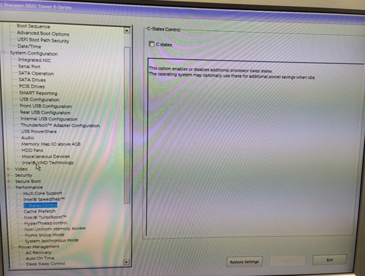
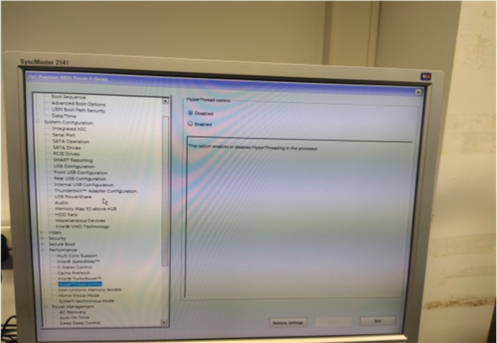
On the gNB system, and on the UE system, if the UE being used is a USRP radio, there are several specific settings that need to be made. The hyperthreading, CPU frequency control, C-states, P-states, and any other power management should all be disabled. Each BIOS will have a different way to do this. The two screenshots below show where in the BIOS menu to disable C-states and to disable Hyperthreading. Once these options are set in the BIOS, reboot the system.
Installing, Configuring, and Running the CN System
This section explains the deployment of the OAI 5G CN system on Ubuntu 20.04 with a generic kernel. The deployment is possible either using docker-compose or Helm Chart. We recommend using docker-compose.
The 5G CN deployment is possible in various forms using docker-compose or Helm Chart.
- Using docker-compose, perform a minimalist deployment
- Using docker-compose, perform a basic deployment
- Using docker-compose, perform a basic-vpp deployment with VPP implementation of UPF
- Using docker-compose, perform a basic deployment with static UE IP address allocation
- Using Helm Chart, perform a basic deployment
- Using docker-compose, doing network slicing
This Application Note explains only the minimalist deployment using docker-compose.
The minimalist deployment can be performed in two scenarios:
- Scenario 1: AMF, SMF, UPF (SPGWU), NRF, MYSQL
- Scenario 2: AMF, SMF, UPF (SPGWU), MYSQL
This Application Note only discusses Scenario 1.
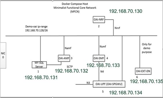
The diagram below shows the layout and architecture of the various Docker containers running on the CN machine, along with the IP address of each container.
Prerequisites for the Scenario 1 Minimalist Deployment
Verify that you are running docker-compose version 1.25 or higher.
dpkg --list | grep docker
Verify that you are running Python version 3.6 or higher.
python3 --version
Note that you should add your username to the docker group so that you can run Docker operations without needing root privileges.
To add your username to the docker group, use the command below.
sudo usermod -a -G docker yourusername
In order to pull the Docker images for the different network functions of the 5G CN, you need to have an account on docker-hub. Use this link to create an account.
Pull Base Images
We need to pull two base Docker images ubuntu:bionic and mysql:5.7.
Log in with your Docker Hub credentials, and push and pull images from Docker Hub.
   docker login
   docker pull ubuntu:bionic
   docker pull mysql:5.7
   docker logout
Be sure to set the following network configuration settings. You must run these commands every time you restart the CN machine, as they will not persist across a reboot.
   sudo sysctl net.ipv4.conf.all.forwarding=1
   sudo iptables -P FORWARD ACCEPT
Pulling the images from Docker Hub
The images are hosted under the OAI account oaisoftwarealliance.
You may need to login to Docker Hub.
docker login
Pull the images listed below.
   docker pull rdefosseoai/oai-amf:latest
   docker pull rdefosseoai/oai-nrf:latest
   docker pull rdefosseoai/oai-spgwu-tiny:latest
   docker pull rdefosseoai/oai-smf:latest
   docker pull rdefosseoai/oai-udr:latest
   docker pull rdefosseoai/oai-udm:latest
   docker pull rdefosseoai/oai-ausf:latest
   docker pull rdefosseoai/oai-upf-vpp:latest
   docker pull rdefosseoai/oai-nssf:latest
Re-tag the images so that the docker-compose files for the tutorial work.
   docker image tag rdefosseoai/oai-amf:latest oai-amf:latest
   docker image tag rdefosseoai/oai-nrf:latest oai-nrf:latest
   docker image tag rdefosseoai/oai-smf:latest oai-smf:latest
   docker image tag rdefosseoai/oai-spgwu-tiny:latest oai-spgwu-tiny:latest
   docker image tag rdefosseoai/oai-udr:latest oai-udr:latest
   docker image tag rdefosseoai/oai-udm:latest oai-udm:latest
   docker image tag rdefosseoai/oai-ausf:latest oai-ausf:latest
   docker image tag rdefosseoai/oai-upf-vpp:latest oai-upf-vpp:latest
   docker image tag rdefosseoai/oai-nssf:latest oai-nssf:latest
Finally, you may logoff. Your token is stored in plain-text.
docker logout
Synchronizing the installed images
Clone the Git repository for the Core Network, and checkout the v1.3.0 tag.
git clone --branch v1.3.0 https://gitlab.eurecom.fr/oai/cn5g/oai-cn5g-fed.git
You may also do this in two discrete steps.
   git clone https://gitlab.eurecom.fr/oai/cn5g/oai-cn5g-fed.git
   git checkout v1.3.0
Next, go into the top-level folder in the repository.
cd oai-cn5g-fed
Next, synchronize all the Git submodules.
./scripts/syncComponents.sh
   ---------------------------------------------------------
   OAI-NRF     component branch : master
   OAI-AMF     component branch : master
   OAI-SMF     component branch : master
   OAI-SPGW-U  component branch : master
   OAI-AUSF    component branch : master
   OAI-UDM     component branch : master
   OAI-UDR     component branch : master
   OAI-UPF-VPP component branch : master
   OAI-NSSF    component branch : master
   ---------------------------------------------------------
   git submodule deinit --all --force
   git submodule init
   git submodule update
Configure the Containers
Configure the Core Network by editing the docker-compose-mini-nrf.yaml file and specifying the proper PLMN, TAC, Operator Key, and DNN, according to the gNB and the UE being used.
If you are using the v1.3.0 tag for the CN code, then specify the PLMN, TAC, and Operator Key in the amf.conf file, according to the gNB and the UE being used. If you are using the newer v1.3.0 tag for the CN code, then do not do this.
User subscription information should be present in the MySQL database before trying to connect the UE. This can be done by adding the UE information into the oai_db1.sql file. Adjust the values shown below with your actual values.
   INSERT INTO users VALUES
       (imsi,msisdn,imei,NULL,'PURGED',50,40000000,100000000,47,0000000000,1,key,0,0,0x40,'ebd07771ace8677a',opc);
Deploy the containers
The containers must be deployed in a strict order for AMF, SMF, and UPF registration with NRF. The data flow sequence must be from the MySQL database, to OAI-NRF, to OAI-AMF, to OAI-SMF, to OAI-UPF.
Installing docker-compose and Wireshark
Install docker-compose onto the Core Network system. The link below provides detailed instructions.
https://www.digitalocean.com/community/tutorials/how-to-install-and-use-docker-compose-on-ubuntu-20-04
Install Wireshark with the commands listed below.
   sudo add-apt-repository ppa:wireshark-dev/stable
   sudo apt update
   sudo apt install wireshark
Check the Wireshark version, and confirm that it is at least version 3.4.7.
wireshark --version
Invoking the Core Network
The Core Network is invoked using a Python script, which is a wrapper for docker-compose and other Docker commands. The script informs the user when the Core Network is correctly configured by checking the health status of containers and checking the connectivity between different Core Network components. Run the commands below.
   cd oai-cn5g-fed/docker-compose
   sudo  python3 ./core-network.py --type start-mini --fqdn no --scenario 1
After running the command, you should see the output listed below.
   root:DEBUG:  Starting 5gcn components... Please wait....
   Creating oai-nrf ... done
   Creating mysql   ... done
   Creating oai-amf ... done
   Creating oai-smf ... done
   Creating oai-spgwu ... done
   Creating oai-ext-dn ... done
   [2021-09-14 16:44:10,098] root:DEBUG:  OAI 5G Core network started, checking the health status of the containers... takes few secs....
   [2021-09-14 16:44:47,025] root:DEBUG:  All components are healthy, please see below for more details....
   Name                 Command                  State                  Ports
   -----------------------------------------------------------------------------------------
   mysql        docker-entrypoint.sh mysqld      Up (healthy)   3306/tcp, 33060/tcp
   oai-amf      /bin/bash /openair-amf/bin ...   Up (healthy)   38412/sctp, 80/tcp, 9090/tcp
   oai-ext-dn   /bin/bash -c  apt update;  ...   Up
   oai-nrf      /bin/bash /openair-nrf/bin ...   Up (healthy)   80/tcp, 9090/tcp
   oai-smf      /bin/bash /openair-smf/bin ...   Up (healthy)   80/tcp, 8805/udp, 9090/tcp
   oai-spgwu    /openair-spgwu-tiny/bin/en ...   Up (healthy)   2152/udp, 8805/udp
   [2021-09-14 16:44:47,025] root:DEBUG:  Checking if the containers are configured....
   [2021-09-14 16:44:47,025] root:DEBUG:  Checking if SMF and UPF registered with nrf core network....
   [2021-09-14 16:44:47,059] root:DEBUG:  For example: oai-smf Registration with oai-nrf can be checked on this url /nnrf-nfm/v1/nf-instances?nf-type="SMF" {"_links":{"item":[{"href":"192.168.70.133"}],"self":""}}....
   [2021-09-14 16:44:47,059] root:DEBUG:  SMF and UPF are registered to NRF....
   [2021-09-14 16:44:47,059] root:DEBUG:  Checking if SMF is able to connect with UPF....
   [2021-09-14 16:44:47,176] root:DEBUG:  UPF receiving heathbeats from SMF....
   [2021-09-14 16:44:47,176] root:DEBUG:  OAI 5G Core network is configured and healthy....
After launching the OAI 5G Core Network, run Wireshark from another terminal.
sudo wireshark
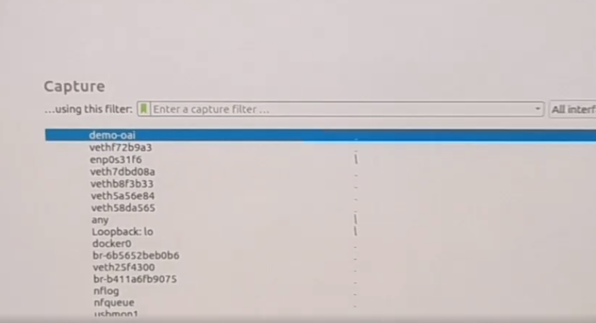
Once Wireshark has launched, you should see the demo-oai network interface listed. Open the demo-oai network interface, and confirm that all the packets exchanged between the different containers such as NRF, AMF, SMF, UPF are shown.
The demo-oai network interface can also be created manually. Since this is not the default behavior, you would need to edit the docker-compose file. The bottom section of the docker-compose-mininrf.yaml should be configured as shown below.
   networks:
       public_net:
           external:
               name: demo-oai-public-net
       # public_net:
       #     driver: bridge
       #     name: demo-oai-public-net
       #     ipam:
       #         config:
       #             - subnet: 192.168.70.128/26
       #     driver_opts:
       #         com.docker.network.bridge.name: "demo-oai"
The docker-compose-host machine needs to be configured with the demo-oai network interface before deploying the core network components. This is needed in order to capture the initial message exchange between the SMF-to-NRF-to-UPF.
   (docker-compose-host)v$ docker network create \
     --driver=bridge \
     --subnet=192.168.70.128/26 \
     -o "com.docker.network.bridge.name"="demo-oai" \
     demo-oai-public-net
   455631b3749ccd6f10a366cd1c49d5a66cf976d176884252d5d88a1e54049bc5
   (docker-compose-host)$ ifconfig demo-oai
   demo-oai: flags=4099<UP,BROADCAST,MULTICAST>  mtu 1500
           inet 192.168.70.129  netmask 255.255.255.192  broadcast 192.168.70.191
           RX packets 0  bytes 0 (0.0 B)
           RX errors 0  dropped 0  overruns 0  frame 0
           TX packets 0  bytes 0 (0.0 B)
           TX errors 0  dropped 0 overruns 0  carrier 0  collisions 0
   (docker-compose-host)$ docker network ls
   NETWORK ID          NAME                  DRIVER              SCOPE
   d2d34e05bb2d        bridge                bridge              local
   455631b3749c        demo-oai-public-net   bridge              local
We will next create a bridge automatically. The bridge can be automatically created using the docker-compose file, if there is no need to capture initial packets. This is the default version in the docker-compose-mini-nrf.yaml file. The bottom section should be configured as shown below.
   networks:
       # public_net:
       #     external:
       #         name: demo-oai-public-net
         public_net:
             driver: bridge
             name: demo-oai-public-net
             ipam:
                 config:
                     - subnet: 192.168.70.128/26
             driver_opts:
                 com.docker.network.bridge.name: "demo-oai"
The screenshots listed below show the Wireshark packet captures for various components when the bridge is built manually.
Showing the SMF request to NRF for subscribing UPF registration/deregistration events:
![]()
Showing the SMF registration with NRF for the PUT request:
![]()
Showing the UPF registration with NRF for the PUT request:
![]()
Showing the NRF notification to SMF for UPF registration for the POST request:
![]()
Showing the SMF-to-UPF PFCP association setup request-and-response:
![]()
These Wireshark packet captures are only visible if you create the demo-oai bridge manually. If the bridge is built automatically, then you will not observe these Wireshark packet captures.
Stopping the Core Network
In order to halt the operation of the Core Network, run the commands listed below.
   cd oai-cn5g-fed/docker-compose
   sudo python3 ./core-network.py --type stop-mini --fqdn no --scenario 1
Installing, Configuring, and Running the gNB System
Before installing and configuring the gNB system, be sure that you first have configured the system BIOS, implemented the Linux performance tuning settings, and installed UHD.
Building and installing the gNB software
The commands listed below build and install the gNB software from source code using the OAI Git repository.
   git clone https://gitlab.eurecom.fr/oai/openairinterface5g.git
   cd openairinterface5g
   git checkout 2022.w33
   source oaienv
   cd cmake_targets
Confirm that you are using the correct branch and commit hash. Run the command listed below, and verify that the branch is 2022.w33 and that the commit hash is ad8381a66bb67d6ef7fa94c9a6ae6c66f3ae84b8.
git status
Edit the build_oai script, and comment out the lines shown below, by adding a hash mark # at the beginning of each line.
   if [ "$HW" == "OAI_USRP" ] ; then
     echo_info "installing packages for USRP support"
     #check_install_usrp_uhd_driver
     #if [ ! "$DISABLE_HARDWARE_DEPENDENCY" == "True" ]; then
     #  install_usrp_uhd_driver $UHD_IMAGES_DIR
     #fi
   fi
For the very first time that you build the gNB software, use the command listed below, which includes the "-I" option, which installs the package dependencies for the gNB software.
./build_oai -I --w USRP
For successive builds, use the command listed below, which omits the "-I" option.
./build_oai --gNB --w USRP
Editing the gNB configuration file
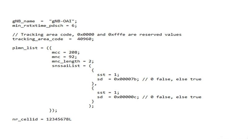
Once the gNB software is built and installed, there are specific settings that need to be made in the gNB configuration file before we can run the gNB software. The folder openairinterface5g/ci_scripts/conf_files contains various configuration files. For this Application Note, we will use the configuration file band78.sa.fr1.106PRB.usrpn310.conf . In this file, change the parameters in the PLMN section. Ensure that the PLMN configuration values are the same as the values used for the CN system, specifically tracking_area_code , mcc , mnc , sst , and sd .
Specifying the AMF IP address
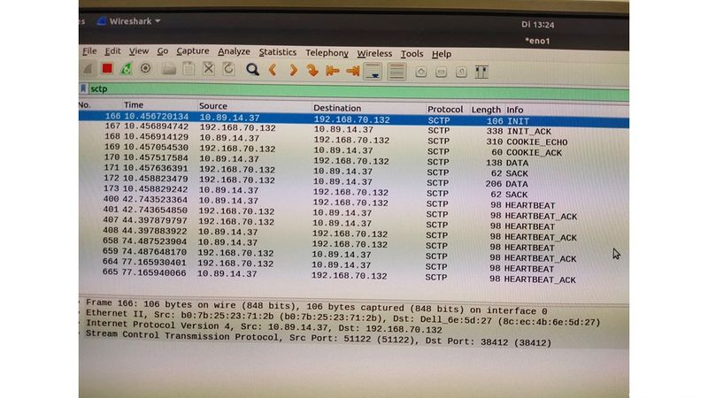
The correct IP address for the AMF needs to be defined in the configuration file, as shown below. In the configuration file, in the AMF parameters section, in the ipv4 field, add the IP address of the AMF Docker container. In this reference architecture, it is 192.168.70.132.
Specifying the gNB IP address
The correct IP address for the gNB needs to be defined in the configuration file, as shown below. In the configuration file, in the NETWORK_INTERFACES section, add the IP address of the gNB system to the GNB_IPV4_ADDRESS_FOR_NG_AMF and the GNB_IPV4_ADDRESS_FOR_NGU fields. In this reference architecture, it is 10.89.14.37.
Specifying the USRP IP address
The correct IP address for the USRP needs to be defined in the configuration file, as shown below. In the configuration file, in the RU section, in the sdr_addrs field, we need to specify the device arguments for the USRP, which includes the type of the USRP (type), the mangement IP address (mgmt_addr), the primary streaming IP address (addr), the secondary streaming IP address (second_addr), the clocking source (clock_source), and the timing source (time_source). In this reference architecture, we use the device argument string listed below.
sdr_addrs="type=x4xx,mgmt_addr=192.168.10.2,addr=192.168.10.2,second_addr=192.168.20.2,clock_source=external,time_source=external"
The mgmt_addr, addr, and second_addr should be defined according to the configuration of your USRP device. For the clock_source and the time source, the values can be internal, external, or gpsdo. In this reference architecture, an OctoClock-G is connected to the USRP, so we use the value of external for both the clocking source and the timing source.
Adding a static route to the CN system
To enable communication between the gNB and CN machine, a static route must be added to the gNB machine. Note that this added route is not permanent, and when the system is restarted, the static route will need to be added again. The command listed below will add the static route.
sudo ip route add 192.168.70.128/26 via 10.89.14.119 dev eno1
In this command, the IP address 192.168.70.128/26 is for the demo-oai network bridge created when the CN is invoked, and the IP address 10.89.14.119 is for the CN machine, and the eno1 Ethernet interface is the port on the gNB machine connected to the CN machine.
On your machine, the Ethernet interface name will likely be different, but you can use the same IP address for the CN machine, and the same static IP address for the CN machine, as used in this reference architecture.
Invoking the gNB
In order to invoke the gNB, we first need to copy the edited gNB configuration file from the folder openairinterface5g/ci_scripts/conf_files to the folder openairinterface5g/targets/PROJECTS/GENERIC-NR-5G/CONF. Then, the command listed below will invoke the gNB.
sudo ./nr-softmodem -O ../../../targets/PROJECTS/GENERIC-NR-5GC/CONF/gnb.band78.sa.fr1.106PRB.usrpn310.conf --sa --usrp-tx-thread-config 1 --thread-pool 0,2,4,6
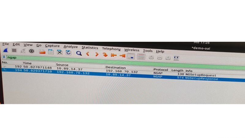
Launch Wireshark, select the Ethernet interface connected to the CN machine, and watch for NGAP packets. As soon as the gNB is launched, the CN and gNB will exchange NGAP setup request and response messages. In these messages, the gNB and CN check the MCC, MNC and TAC parameters. If these values are identical on both the gNB machine and the CN machine, then the NGAP setup request and response will be successful.
Interfaces Between gNB and Core Network
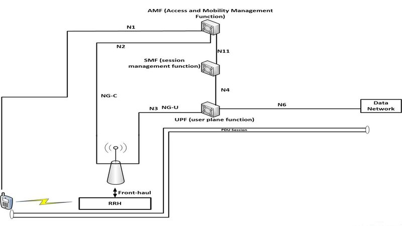
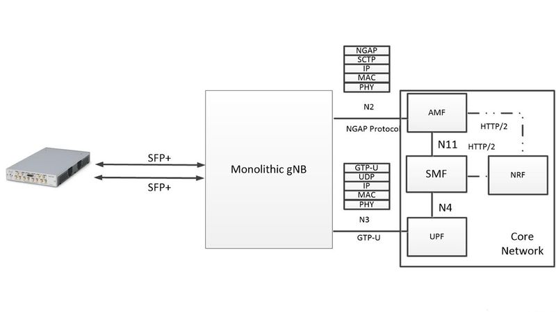
When the gNB is invoked, the N2 and N3 interfaces will be created. The N2 interface supports the NGAP protocol, and the N3 interface supports the GTP protocol. The N1 interface is created when UE attaches to the network and supports the NAS protocol.
Testing Connectivity Between gNB and CN
Once both the gNB and the CN machines are up-and-running, test the connectivity between the two systems by pinging the AMF in the CN machine from the gNB machine. On the gNB machine, run the command listed below.
ping 192.168.70.132
If the ping fails, then it may be due to the firewall settings. On the CN machine, run the commands listed below to configure the firewall.
   sysctl net.ipv4.conf.all.forwarding=1
   sudo iptables -P FORWARD ACCEPT
After running these commands on the CN machine, run this command on the gNB machine to add a route from the gNB machine to the CN machine. You will likely need to replace the Ethernet interface name eno1 with the correct interface name on your gNB machine.
sudo ip route add 192.168.70.128/26 via 10.89.14.6 dev eno1
The IP address 192.168.70.128/26 is for the demo-oai interface, and 10.89.14.6 is the IP address of the CN machine, and eno1 is the Ethernet interface name on the gNB machine.
Installing, Configuring, and Running the UE System
There are three scenarios for the UE implementation: the USRP radio; the 5G wireless modem module; and the COTS handset.
UE Scenario 1: USRP
The UE can be implemented by running the OAI softmodem with a USRP N300, N310, N320, N321, or X410 device. Currently, this reference architecture is focused on the use of a USRP X410 device, although the integration of the other USRP devices is similar to the integration of the USRP X410 and is relatively straight-forward.
Before installing and configuring the UE system, be sure that you first have configured the system BIOS, implemented the Linux performance tuning settings, and installed UHD.
Building and installing the OAI softmodem software
Note that the procedure for building and configuring the UE software is very similar to the procedure for building and installing the gNB software.
The commands listed below build and install the UE software from source code using the OAI Git repository.
   git clone https://gitlab.eurecom.fr/oai/openairinterface5g.git
   cd openairinterface5g
   git checkout 2022.w33
   source oaienv
   cd cmake_targets
Confirm that you are using the correct branch and commit hash. Run the command listed below, and verify that the branch is 2022.w33 and that the commit hash is ad8381a66bb67d6ef7fa94c9a6ae6c66f3ae84b8.
git status
Edit the build_oai script, and comment out the lines shown below, by adding a hash mark # at the beginning of each line.
   if [ "$HW" == "OAI_USRP" ] ; then
     echo_info "installing packages for USRP support"
     #check_install_usrp_uhd_driver
     #if [ ! "$DISABLE_HARDWARE_DEPENDENCY" == "True" ]; then
     #  install_usrp_uhd_driver $UHD_IMAGES_DIR
     #fi
   fi
For the very first time that you build the gNB software, use the command listed below, which includes the "-I" option, which installs the package dependencies for the gNB software.
./build_oai -I --w USRP
For successive builds, use the command listed below, which omits the "-I" option.
./build_oai --gNB --w USRP
Editing the UE Configuration File
Once we build and install the UE software, we need to modify the UE configuration file. Only one UE configuration file is available in the folder openairinterface5g/targets/PROJECTS/GENERIC-NR-5GC/CONF. The UE configuration file used in this reference architecture is ue.conf. The default contents of the file is shown below.
   uicc0 = {
   imsi = "2089900007487";
   key = "fec86ba6eb707ed08905757b1bb44b8f";
   opc= "C42449363BBAD02B66D16BC975D77CC1";
   dnn= "oai";
   nssai_sst=1;
   nssai_sd=1;
   }
Edit the fields imsi, key, opc, dnn, nssai_sst, nssai_sd per the values for the CN. Earlier, when configuring the Docker containers for the CN system, we entered several parameters in the oai_db1.sql file. The imsi, key, opc fields there should match the values here in the UE configuration file. The dnn value should be same as listed in the docker-compose-mini-nrf.yaml<code> file. The <code>nssai_sst and nssai_sd values should be same as listed in the gNB configuration file and the docker-compose-mini-nrf.yaml file.
Invoking the OAI UE softmodem
Run the command listed below to invoke the OAI UE softmodem.
openairinterface5g/cmake_targets/ran_build/build sudo ./nr-uesoftmodem --usrp-args "addr=192.168.10.2, clock_source=external,time_source=external" -r 106 --numerology 1 --band 78 -C 3319680000 --sa --nokrnmod 1 -O ../../../targets/PROJECTS/GENERIC-NR-5GC/CONF/ue.conf
The command-line option --usrp-args specifies the USRP device arguments, which are passed to the UHD driver. Here we specify the IP address of the USRP, along with clocking source and the timing source, which are set to external, to indicate the use of the connection to the OctoClock-G device.
The command-line option -r 106 specifies the PRBS being used. Based on the PRBS, we can calculate the operational channel bandwidth being used (i.e., 40 MHz).
The command-line option --numerology 1 specifies the SCS being used (i.e., 30 KHz).
The command-line option --band 78 specifies the 3GPP frequency band being used.
The command-line option -C 3319680000 specifies the CF we are operating (i.e., 3.319 GHz).
The command-line option --nokrnmod 1 forces the use of the tunnel interface.
Once the UE is attached to the CN, verify that the oaitun_ue1 network interface has been created, and that is has been assigned an IP address of 10.x.x.x, using the command listed below.
ifconfig
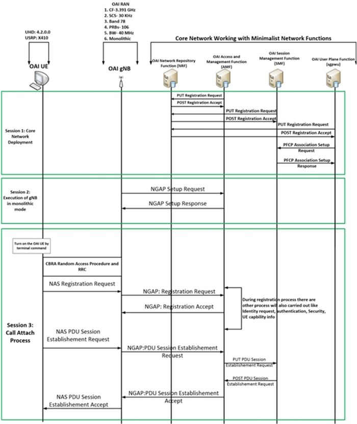
The call attach process between the UE and the gNB is illustrated in the sequence diagram shown below.
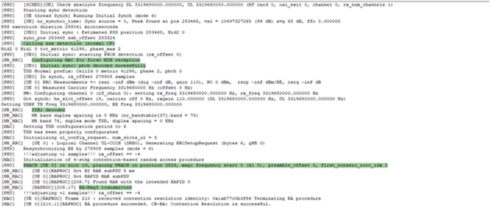
The relevant lines in the OAI UE softmodem log file show information about the call attach process.
Launch Wireshark to view the packets exchanged between the UE and gNB for this call attach process.
Verify that the UE was connected to the gNB
To verify that UE has successfully attached to the gNB, check the OAI-AMF logs on the CN machine using the command listed below. Check the output to confirm that UE has been registered by the Core Network.
sudo docker logs oai-amf
Run ifconfig on the UE machine to check the IP address assigned to the UE. Verify that the oaitun_ue1 network interface has been created, and that is has been assigned an IP address of 10.x.x.x. You can also check the OAI-SMF logs using the command listed below.
sudo docker oai-smf logs
UE Scenario 2: 5G Wireless Modem Module
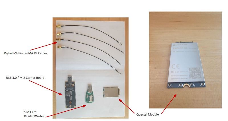
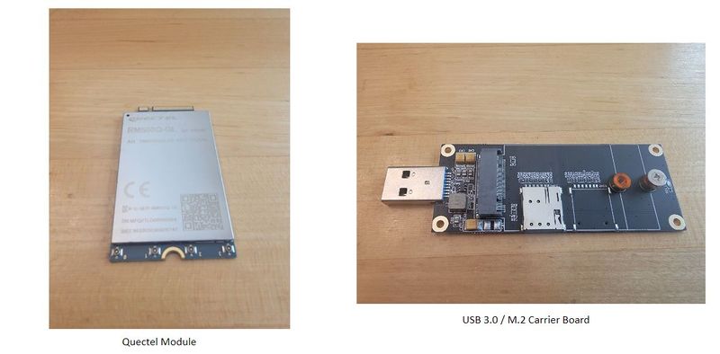
The UE can be implemented using a 5G wireless modem module. Currently, this reference architecture is focused on the use of a Quectel RM500Q-GL 5G wireless modem module. This device is a 5G NR sub-6GHz M.2 module which meets the 3GPP Release 15 specification, and is optimized for industrial and commercial IoT and eMBB applications. It supports both standalone (SA) and non-standalone (NSA) modes. Other wireless modem modules can certainly be used as well. Detailed documentation for the Sierra Wireless EM9191 module will be added in the near future.
Configuring the SIM Card
When using a 5G wireless modem module or a COTS handset, a SIM card will be required. If a USRP is being used as the UE, running the OAI UE softmodem, then a SIM card is not required.
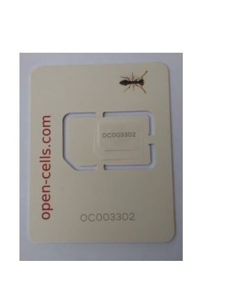
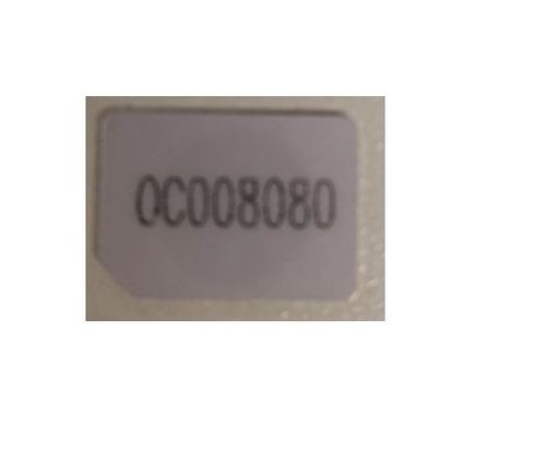
The SIM card used in this reference architecture is provided by Open-Cells, and is shown below. Note that the ADM code is printed directly on the SIM card itself.
Insert the nano SIM card into the SIM card reder/writer, and plug it into the USB slot on the UE computer.
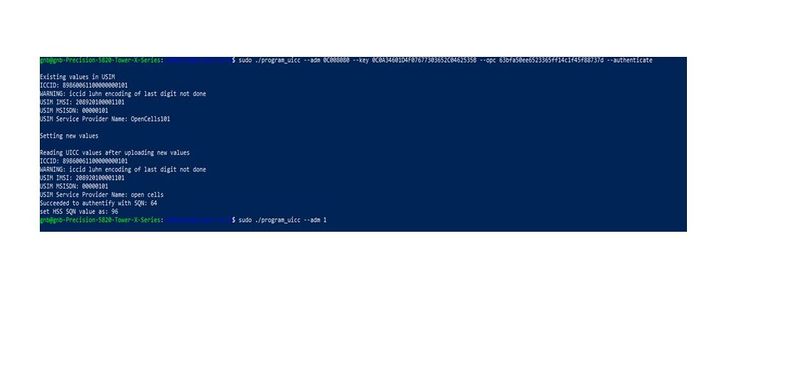
To read and program the SIM card, we use the program program_uicc from Open-Cells (here).
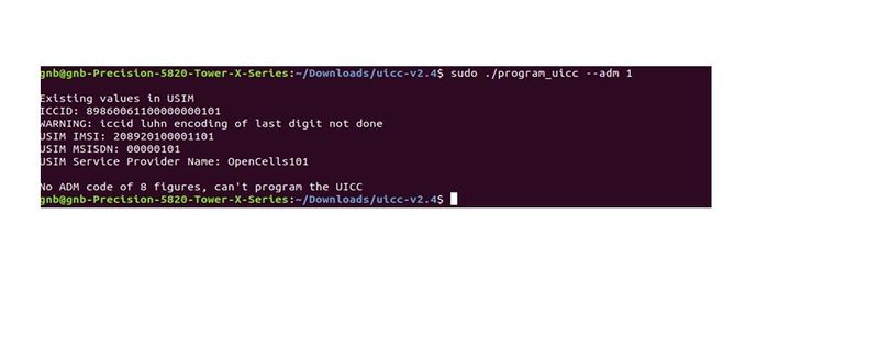
We first read the existing data on the SIM by running the command below.
sudo ./program_uicc --adm 1
We then write the key and the OPC in the UICC file in the SIM card. The ADM value enables this. Run the command below to perform this operation, where ADM_VALUE_FROM_SIM is the ADM value printed directly on the SIM card itself.
sudo ./program_uicc --adm <ADM_VALUE_FROM_SIM> --key 0C0A34601D4F07677303652C0462535B --opc 63bfa50ee6523365ff14c1f45f88737d --authenticate --noreadafter
Ensure that the values being programmed into the SIM card match the corresponding values entered in the SQL database on the CN machine. The values of primary importance are listed in the table below.
| Parameter | UE | gNB | CN |
|---|---|---|---|
| IMSI | 208920100001101 |
MCC: 208, MNC: 92 |
208920100001101
|
| MSISDN | 00000101 |
00000101
| |
| IMEI | 863305040549338 |
863305040549338
| |
| Key | 0C0A34601D4F07677303652C0462535B |
0C0A34601D4F07677303652C0462535B
| |
| OPC | 63bfa50ee6523365ff14c1f45f88737d |
63bfa50ee6523365ff14c1f45f88737d
|
Serial Connection to the Module via Minicom
Attach all four antennas to the Quectel wireless modem module. Then, mount the Quectel module into the M.2 connector slot on the carrier board. Then, connect the carrier board to the UE computer via a USB 3.0 port.
We will use Minicom to communicate with the Quectel module over a USB serial connection. Run which minicom to verify that Minicom is already installed. If not, then run the command listed below to install it.
sudo apt-get install minicom
Once the Quectel module is plugged in, the Linux operating system should create several USB serial devices which can be used to communicate with the module. The default device should be /dev/ttyUSB0. Run the command listed below to start a Minicom serial console session with the Quectel device.
sudo minicom /dev/ttyUSB0
Note that in order to exit Minicom, type Ctrl-A, then "X".
AT Commands for the Module
We use Minicom to issue AT Commands to the 5G modem module.
There are informative articles about AT Commands here and here.
There are some specific AT Commands that we need to control and query the Quectel module. The AT Command are generally not case-sensitive. Execute all the AT Commands listed below, in-order, to setup and configure the Quectel module.
-
AT+GMR - Display the current firmwave version number.
-
AT+CIMI - Display the IMSI of the (U)SIM.
-
AT+GSN - Display the IMEI of the (U)SIM.
-
AT+QMBNCFG="select","ROW_Commercial" - Unlock the Quectel module.
-
AT+qnwprefcfg="nr5g_band" - Display which 5G NR frequency bands are configured.
-
AT+qnwprefcfg="mode_pref" - Display which 5G NR mode is set.
-
AT+qnwprefcfg="mode_pref",nr5g - Set the operational mode to 5G NR SA.
-
AT+qnwprefcfg="nr5g_disable_mode",0 - Enable 5G NR operations.
-
AT+cgdcont=1,“IP“,“oai“,“0.0.0.0“,0,0 (cid, pdp type, apn, pdp_addr, data_comp, head-comp) - Specify the PDP context parameters for a specific context cid.
-
AT+CFUN=0 - Set the minimum functionality of the module.
-
AT+CFUN=1 - Set the full functionality of the module.
Verifying the Operation with Wireshark
Once all the AT Commands have been executed, we should see msg1, msg2, msg3, msg4, RRC logs on the gNB and the registration request from the UE to the AMF on Wireshark.
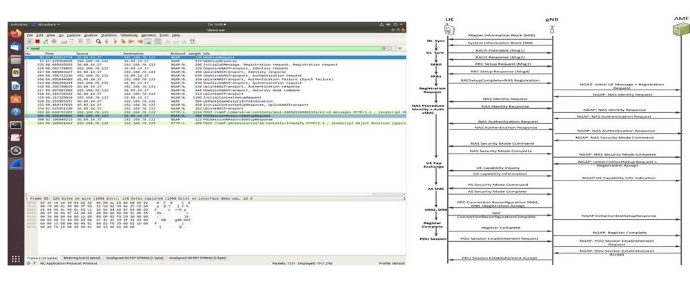
The screenshot below shows Wireshark running on the CN machine, and shown on the right is the corresponding sequence diagram showing the message exchanges between the UE, gNB, and CN AMF, from the perspective of the CN machine.
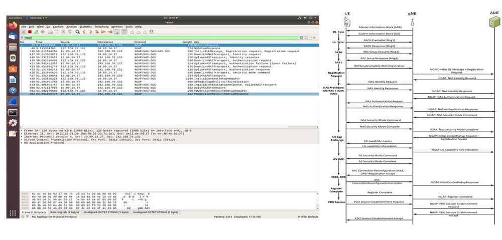
The screenshot below shows Wireshark running on the gNB machine, and shown on the right is the corresponding sequence diagram showing the message exchanges between the UE, gNB, and CN AMF, from the perspective of the gNB machine.
Verifying the Operation with AT Commands
We run the AT Commands listed below in Minicom, and examine the responses, to verify the operation of the system.
-
AT+COPS? - This output specifies the current operators and their status.
- Expected Output:
0,0,"208 92 open cells",11 - Field 1: Availability of Operators, where
0specifies Unknown - Field 2: Operator Selection of operators, where
0specifies Automatic - Field 3: Operator Name, where
208 92 Open cellspecifies pre-programmed operator name - Field 4: Access Technology Selected, where
11specifies 5G NR connected to a 5G CN
-
AT+C5GREG? - The output of this command shows the 5G network registration status.
- Expected Output:
2,1,"1","0",11,16,"01.00007B;00.000000:01.00000C;00.000000" - Field 1: Enable network registration and location information, where
2specifies Unsolicited Mode - Field 2: Registration Status, where
1specifies Registered on Home Network - Field 3:
1specifies a three-byte tracking area code in hexadecimal format - Field 4:
0specifies a five-byte (NR) cell ID in hexadecimal format - Field 5:
11specifies that the connection mode is 5G NR connected to a 5G CN - Field 6:
16specifies the number of octets of the allowed NSSAI information element - Field 7:
01.00007B;00.000000:01.00000C;00.000000specifies the allowed NSSAI
UE Scenario 3: COTS Handset
The UE can be implemented using the commercial (COTS) handset. This reference architecture will feature the use of the Google Pixel 5A handset. Detailed documentation about this will be added in the near future.
End-to-End Verification
Using ping
We run ping on the CN machine to verify connectivity from the CN, through the gNB, to the UE. Run the command listed below on the CN machine. Replace 12.1.1.x with the correct IP address of the UE, as assigned by the CN.
sudo docker exec –it oai-ext-dn ping 12.1.1.x
Using iperf
We use iperf to measure the throughput in bits per second for the Downlink (DL) and for the Uplink (UL).
Downlink
For the Downlink, the client runs on the CN machine, and the server runs on the UE machine.
Run the command listed below on the client. Replace 12.1.1.x with the correct IP address of the UE, as assigned by the CN.
sudo docker exec –it oai-ext-dn iperf –c 12.1.1.x –u –b yM --bind 192.168.70.135
Run the command listed below on the server. Replace 12.1.1.x with the correct IP address of the UE, as assigned by the CN.
iperf –s –i 1 –u –B 12.1.1.x
Uplink
For the Uplink, the client runs on the UE machine, and the server runs on the CN machine.
Run the command listed below on the client. Replace 12.1.1.x with the correct IP address of the UE, as assigned by the CN.
iperf –c 192.168.70.135 –u –b yM --bind 12.1.1.x
Run the command listed below on the server. Replace 12.1.1.x with the correct IP address of the UE, as assigned by the CN.
sudo docker exec –it oai-ext-dn iperf –s –i 1 -u –B 192.168.70.135
Technical Support
The primary method of technical support is through mailing lists and direct email.
USRP Mailing List
The usrp-users mailing list is for discussions specifically involving the USRP hardware and the UHD software.
https://lists.ettus.com/list/usrp-users.lists.ettus.com
The list archives can be found at the link below.
https://lists.ettus.com/empathy/list/usrp-users.lists.ettus.com
OAI Mailing List
There are two mailing lists, openair5g-user and openair5g-nr, which are for discussions specifically involving the Open Air Interface (OAI) software stack. More information can be found at the links below.
https://gitlab.eurecom.fr/oai/openairinterface5g/-/wikis/MailingList
https://gitlab.eurecom.fr/oai/openairinterface5g/-/wikis/AskQuestions
You can contact the authors about the reference architecture directly via email at [email protected].

