Difference between revisions of "Modifying an X310 Chassis for External LO Sharing"
From Ettus Knowledge Base
(→Steps) |
(→Application Note Number) |
||
| (39 intermediate revisions by the same user not shown) | |||
| Line 1: | Line 1: | ||
==Application Note Number== | ==Application Note Number== | ||
| − | '''AN- | + | '''AN-355''' |
| − | + | ||
==Revision History== | ==Revision History== | ||
| Line 9: | Line 8: | ||
!Details | !Details | ||
|- | |- | ||
| − | |style="text-align:center;"| 2019- | + | |style="text-align:center;"| 2019-10-02 |
|style="text-align:center;"| Sam Reiter | |style="text-align:center;"| Sam Reiter | ||
|style="text-align:center;"| Initial creation | |style="text-align:center;"| Initial creation | ||
| Line 15: | Line 14: | ||
==Overview== | ==Overview== | ||
| − | This document describes how to modify an X310 chassis to wire the LO | + | This document describes how to modify an X310 chassis to wire the LO out of the back plate. Doing this will allow the user to export and import an LO signal as desired when using a compatible daughterboard such as the TwinRX. Tools and cables are not available for purchase from Ettus Research, but product recommendations are made. All modifications are performed at the user's own risk. |
==Product Compatibility== | ==Product Compatibility== | ||
| Line 33: | Line 32: | ||
Example Manufacturer: Cinch Connectivity Solutions Johnson | Example Manufacturer: Cinch Connectivity Solutions Johnson | ||
| − | Example Part Number: 415-0073-MM250 | + | Example Part Number: 415-0073-MM250 |
| + | |||
| + | [[File:SMAtoMMCX.jpg|200px|center]] | ||
==Steps== | ==Steps== | ||
| Line 39: | Line 40: | ||
#* There are two Phillips head screws to remove | #* There are two Phillips head screws to remove | ||
#* Use the notch in the case to lift up and slide back the cover | #* Use the notch in the case to lift up and slide back the cover | ||
| − | + | #:[[File:TopCover.jpg|900px|center]] | |
| − | # Remove the | + | #:<center>''X310 Cover Screws and Notch''</center> |
| − | #* There are four Torx | + | # Remove the back plate of the X310 |
| + | #* There are four Torx t8 screws to remove | ||
#* There are 5 nuts around the PPS I/O, REF I/O, and GPS SMA connectors | #* There are 5 nuts around the PPS I/O, REF I/O, and GPS SMA connectors | ||
| + | #:[[File:BackWithHW.JPG|900px|center]] | ||
| + | #:<center>''X310 Back Plate''</center> | ||
#* Slide the back plate directly out from the rear of the device to remove. | #* Slide the back plate directly out from the rear of the device to remove. | ||
| − | + | #:[[File:BackWOHW.jpg|900px|center]] | |
| + | #:<center>''X310 Back Plate Removal''</center> | ||
# Cut holes in the backplate sticker as appropriate | # Cut holes in the backplate sticker as appropriate | ||
#* There are 6 holes pre-drilled in the backplate, no need for any drilling or modifying of the aluminium case. | #* There are 6 holes pre-drilled in the backplate, no need for any drilling or modifying of the aluminium case. | ||
#* Note, if you don't have these pre-drilled holes, ensure your chassis P/N matches those in the "Product Compatibility" section. | #* Note, if you don't have these pre-drilled holes, ensure your chassis P/N matches those in the "Product Compatibility" section. | ||
#* NI-Branded USRPs with TwinRX boards such as the NI-2945 and NI-2955 use these holes with a product specific sticker. A picture of this is included below, for reference. | #* NI-Branded USRPs with TwinRX boards such as the NI-2945 and NI-2955 use these holes with a product specific sticker. A picture of this is included below, for reference. | ||
| + | #:[[File:backplate nohardware.jpg|900px|center]] | ||
| + | #:<center>''NI-2955 Back Plate Hole Configuration''</center> | ||
| + | #:[[File:2945backplatw hardware.JPG|900px|center]] | ||
| + | #:<center>''NI-2955 Back Plate with Hardware Populated''</center> | ||
| + | # Replace the back plate of the X310 | ||
| + | #* This process is the opposite of removal (see step 2) | ||
| + | # Add the new SMA cables to the holes in the chassis | ||
| + | #* Unscrew the nut from each SMA, push it through the back of the device, and replace the nut + lock washer. | ||
| + | #:[[File:AddSMA.jpg|900px|center]] | ||
| + | #:<center>''X310 Back Plate With SMA to MMCX Cables''</center> | ||
| + | # Connect the MMCX connectors to the TwinRX boards | ||
| + | #* See the [https://kb.ettus.com/TwinRX_Getting_Started_Guides TwinRX Getting Started Guide] for details regarding connections | ||
| + | #* When routing cables, it's recommended to place them between the daughterboard and heat sync. Cables on top of the TwinRX or heat sync may cause lid clearance issues. | ||
| + | # Additional Notes | ||
| + | #* Unfortunately, there is currently no replacement sticker available to add to an Ettus-branded X310. Labels will need to be DIY, if desired. | ||
| + | #* Performing this change to an X310 with a part number listed in the "Product Compatibility" section will not void its warranty. | ||
| + | #* If you have an X310 that is not listed in the "Product Compatibility" section and want to perform this modification, contact support@ettus.com for measurements and appropriate disclaimers. | ||
| − | == | + | ==Configuration Options== |
| − | === | + | ===8 Channel RX, Star Configuration, External LO=== |
| − | * | + | * Green and blue cables are external connections and components |
| − | * | + | *:[[File:Star.png|1000px|center]] |
| − | + | ||
| − | [[File: | + | |
| − | + | ||
| − | + | ||
| − | + | ||
| − | + | ||
| − | + | ||
| − | + | ||
| − | + | ||
| − | + | ||
| − | + | ||
| − | + | ||
| − | + | ||
| − | + | ||
| − | + | ||
| − | + | ||
| − | + | ||
| − | + | ||
| − | + | ||
| − | + | ||
| − | + | ||
| − | + | ||
| − | + | ||
| − | + | ||
| − | + | ||
| − | + | ||
| − | + | ||
| − | + | ||
| − | + | ||
| − | + | ||
| − | + | ||
| − | + | ||
| − | + | ||
| − | + | ||
| − | + | ||
| − | + | ||
| − | + | ||
| − | + | ||
| − | + | ||
| − | + | ||
| − | + | ||
| − | + | ||
| − | + | ||
| − | + | ||
| − | + | ||
| − | + | ||
| − | + | ||
| − | + | ||
| − | + | ||
| − | + | ||
| − | + | ||
| − | + | ||
| − | + | ||
| − | + | ||
| − | + | ||
| − | + | ||
| − | + | ||
| − | + | ||
| − | == | + | ===8 Channel RX, Daisy-Chain Configuration=== |
| − | + | * Green and blue cables are external connections and components | |
| + | * Make sure to measure LO power at each stage. Active splitters or amplifiers are recommended, especially with larger daisy-chain configurations. | ||
| + | *:[[File:DaisyChain.png|1000px|center]] | ||
| − | + | ==Additional Notes== | |
| + | [https://kb.ettus.com/TwinRX_Getting_Started_Guides TwinRX Getting Started Guide] | ||
[[Category:Application Notes]] | [[Category:Application Notes]] | ||
Latest revision as of 15:59, 15 October 2019
Contents
Application Note Number
AN-355
Revision History
| Date | Author | Details |
|---|---|---|
| 2019-10-02 | Sam Reiter | Initial creation |
Overview
This document describes how to modify an X310 chassis to wire the LO out of the back plate. Doing this will allow the user to export and import an LO signal as desired when using a compatible daughterboard such as the TwinRX. Tools and cables are not available for purchase from Ettus Research, but product recommendations are made. All modifications are performed at the user's own risk.
Product Compatibility
This guide is only for devices with following Part Numbers:
- 156485C-09L
- 156485C-10L
- 156485F-09L
- 156485F-10L
- 156485G-09L
- 156485G-10L
Cable Recommendation
Cable type: SMA (F) to Right-angle MMCX (M) Cable Assembly Cable Length: 25cm
Example Manufacturer: Cinch Connectivity Solutions Johnson Example Part Number: 415-0073-MM250

Steps
- Remove the top cover of the X310
- There are two Phillips head screws to remove
- Use the notch in the case to lift up and slide back the cover
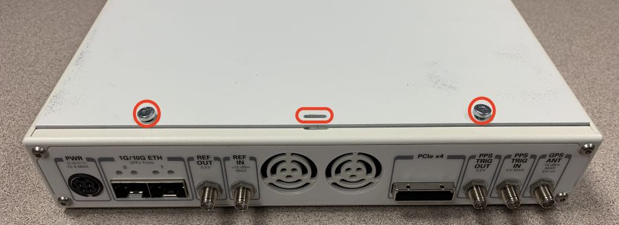
X310 Cover Screws and Notch
- Remove the back plate of the X310
- There are four Torx t8 screws to remove
- There are 5 nuts around the PPS I/O, REF I/O, and GPS SMA connectors
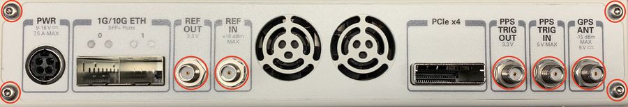
X310 Back Plate
- Slide the back plate directly out from the rear of the device to remove.
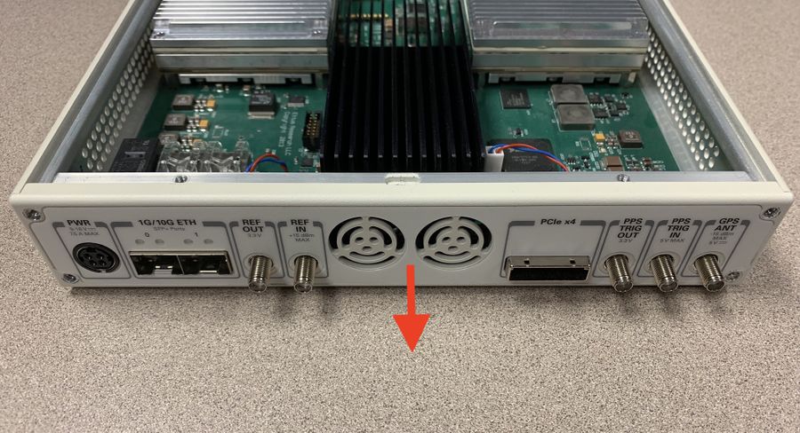
X310 Back Plate Removal
- Cut holes in the backplate sticker as appropriate
- There are 6 holes pre-drilled in the backplate, no need for any drilling or modifying of the aluminium case.
- Note, if you don't have these pre-drilled holes, ensure your chassis P/N matches those in the "Product Compatibility" section.
- NI-Branded USRPs with TwinRX boards such as the NI-2945 and NI-2955 use these holes with a product specific sticker. A picture of this is included below, for reference.
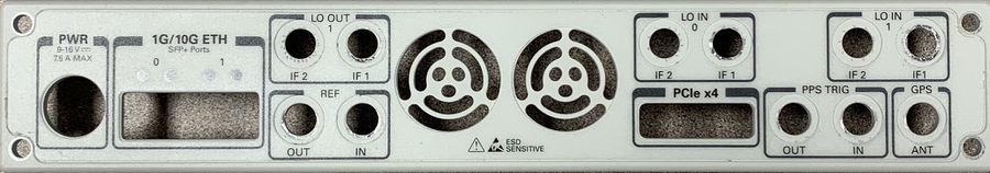
NI-2955 Back Plate Hole Configuration 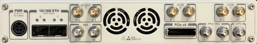
NI-2955 Back Plate with Hardware Populated
- Replace the back plate of the X310
- This process is the opposite of removal (see step 2)
- Add the new SMA cables to the holes in the chassis
- Unscrew the nut from each SMA, push it through the back of the device, and replace the nut + lock washer.
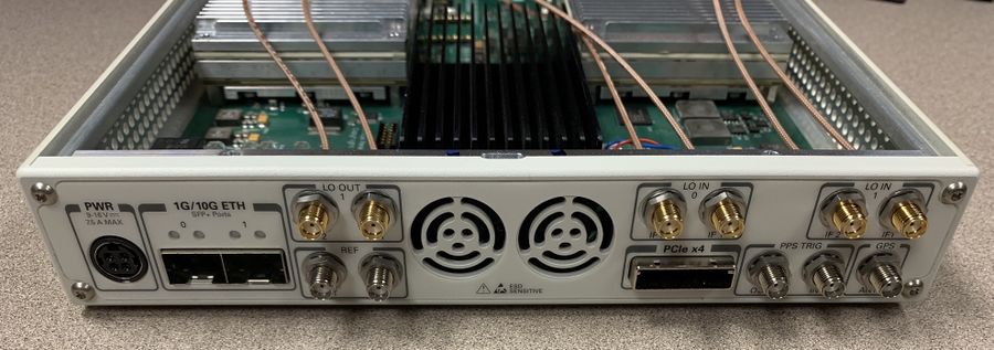
X310 Back Plate With SMA to MMCX Cables
- Connect the MMCX connectors to the TwinRX boards
- See the TwinRX Getting Started Guide for details regarding connections
- When routing cables, it's recommended to place them between the daughterboard and heat sync. Cables on top of the TwinRX or heat sync may cause lid clearance issues.
- Additional Notes
- Unfortunately, there is currently no replacement sticker available to add to an Ettus-branded X310. Labels will need to be DIY, if desired.
- Performing this change to an X310 with a part number listed in the "Product Compatibility" section will not void its warranty.
- If you have an X310 that is not listed in the "Product Compatibility" section and want to perform this modification, contact support@ettus.com for measurements and appropriate disclaimers.


Configuration Options
8 Channel RX, Star Configuration, External LO
- Green and blue cables are external connections and components

8 Channel RX, Daisy-Chain Configuration
- Green and blue cables are external connections and components
- Make sure to measure LO power at each stage. Active splitters or amplifiers are recommended, especially with larger daisy-chain configurations.
