X300/X310
Contents
- 1 Device Overview
- 2 Key Features
- 3 Compatible Daughterboards
- 4 RF Specifications
- 5 Hardware Specifications
- 6 Physical Specifications
- 7 Environmental Specifications
- 8 Schematics
- 9 Key Component Datasheets
- 10 GPSDO
- 11 Mechanical Information
- 12 FPGA
- 13 Interfaces and Connectivity
- 14 Certifications
- 15 Certificate of Volatility
- 16 Downloads
- 17 Choosing USRP X310 vs USRP X300
- 18 Choosing an RF Daughterboard
- 19 Choosing a Host Interface
- 20 International Power Supply Options
- 21 Option: GPS Disciplined, Oven-Controlled Oscillator (GPSDO)
- 22 Option: Antenna Kit for GPSDO
- 23 Option: General Purpose Input/Output (GPIO) Kit
- 24 Option: Cables for MIMO Expansion
- 25 Option: USRP X300/X310 Rackmount
- 26 Guidance on SFP+ Adapters for Fiber Connectivity on USRP X300/X310
- 27 FAQ
Device Overview
The Ettus Research USRP X310 is a high-performance, scalable software defined radio (SDR) platform for designing and deploying next generation wireless communications systems. The hardware architecture combines two extended-bandwidth daughterboard slots covering DC – 6 GHz with up to 160 MHz of baseband bandwidth, multiple high-speed interface options (PCIe, dual 10 GigE, dual 1 GigE), and a large user-programmable Kintex-7 FPGA in a convenient desktop or rack-mountable half-wide 1U form factor.
Key Features
X300
|
X310
|
Compatible Daughterboards
- WBX-120 / WBX-40
- SBX-120 / SBX-40
- CBX-120 / CBX-40
- UBX-160 / UBX-40
- BasicTX / BasicRX
- LFRX / LFTX
- TwinRX
- DBSRX2 (EOL)
- RFX Series (EOL)
- TVRX2 (EOL)
RF Specifications
RF Performance Data (with SBX-120)
- SSB/LO Suppression -35/50 dBc
- Phase Noise 3.5 GHz 1.0 deg RMS
- Phase Noise 6 GHz 1.5 deg RMS
- Power Output >10dBm
- IIP3 (@ typ NF) 0dBm
- Typical Noise Figure 8dB
Hardware Specifications
- Ettus Research recommends to always use the latest stable version of UHD
X300
- Current Hardware Revision: 8
- Minimum version of UHD required: 3.9.0
X310
- Current Hardware Revision: 8
- Minimum version of UHD required: 3.9.0
Physical Specifications
Dimensions
27.7 x 21.8 x 3.9 cm
Environmental Specifications
Operating Temperature Range
- X300/X310 0-40 °C
Operating Humidity Range
- 10% to 90% non-condensing
Schematics
X300/X310
Key Component Datasheets
| Part Number | Description | Schematic ID (Page) |
|---|---|---|
| XC7K325T / XC7K410T | FPGA | U23 (3,5,8,9,10,18) |
| AD9146 | Dual Channel, 16-Bit, 1230 MSPS DAC | U12, U36 (7) |
| ADS62P48 | Dual Channel, 14-Bit 210 MSPS ADC | U11, U35 (6) |
| FIN1002 | High Speed Differential Receiver | U3, U5, U31, U32 (4) |
| 24LC256T | EEPROM | U530 (11) |
| LMK04816BISQ/NOPB_1/3 | Jitter Cleaner With Dual Loop PLLs | U531 (11) |
| SY89547LMGTR | Multiplexer | U506 (12) |
| SN74AUP1T17 | Single Schmitt-Trigger Buffer Gate | U6, U519 (12) |
| TPS54620RGYT | Synchronous Step Down SWIFT™ Converter | U515 (21); U516 (26) |
| LT1764EQ-3.3 | Voltage Regulator | U27 (21); U516 (26) |
| TPS7A47 | Voltage Regulator | U28, U532 (21) |
| LTC3603EUF_TRPBF | Monolithic Synchronous Step-Down Regulator | U517 (23); U500 (25); U514, U513 (27) |
| TPS77625_SM | Low-Dropout Voltage Regulators | U30 (23) |
| TPS79318_SM | Low-Dropout Voltage Regulators | U510 (27) |
| OSC-96MHZ-724821-01 | Voltage Controlled Crystal Oscillator | U25 (11) |
GPSDO
- Support GPSDO NMEA Strings
- JacksonLabs LC_XO
Sensors
You can query the lock status with the gps_locked sensor, as well as obtain raw NMEA sentences using the gps_gprmc, and gps_gpgga sensors. Location information can be parsed out of the gps_gpgga sensor by using gpsd or another NMEA parser.
Mechanical Information
Weight
With 2x SBX-120: 1.7kg
Drawings
FPGA
- Utilization statistics are subject to change between UHD releases. This information is current as of UHD 3.9.4 and was taken directly from Xilinx Vivado 2014.4.
X300
1. Slice Logic
--------------

+----------------------------+-------+-----------+-------+
|          Site Type         |  Used | Available | Util% |
+----------------------------+-------+-----------+-------+
| Slice LUTs                 | 61622 |    203800 | 30.23 |
|   LUT as Logic             | 52887 |    203800 | 25.95 |
|   LUT as Memory            |  8735 |     64000 | 13.64 |
|     LUT as Distributed RAM |  1878 |           |       |
|     LUT as Shift Register  |  6857 |           |       |
| Slice Registers            | 62961 |    407600 | 15.44 |
|   Register as Flip Flop    | 62961 |    407600 | 15.44 |
|   Register as Latch        |     0 |    407600 |  0.00 |
| F7 Muxes                   |  1209 |    101900 |  1.18 |
| F8 Muxes                   |   150 |     50950 |  0.29 |
+----------------------------+-------+-----------+-------+

3. Memory
---------

+-------------------+------+-----------+-------+
|     Site Type     | Used | Available | Util% |
+-------------------+------+-----------+-------+
| Block RAM Tile    |  409 |       445 | 91.91 |
|   RAMB36/FIFO*    |  398 |       445 | 89.43 |
|     RAMB36E1 only |  398 |           |       |
|   RAMB18          |   22 |       890 |  2.47 |
|     RAMB18E1 only |   22 |           |       |
+-------------------+------+-----------+-------+
* Note: Each Block RAM Tile only has one FIFO logic available and therefore can accommodate only one FIFO36E1 or one FIFO18E1. However, if a FIFO18E1 occupies a Block RAM Tile, that tile can still accommodate a RAMB18E1


4. DSP
------

+----------------+------+-----------+-------+
|    Site Type   | Used | Available | Util% |
+----------------+------+-----------+-------+
| DSPs           |  123 |       840 | 14.64 |
|   DSP48E1 only |  123 |           |       |
+----------------+------+-----------+-------+
X310
1. Slice Logic
--------------

+----------------------------+-------+-----------+-------+
|          Site Type         |  Used | Available | Util% |
+----------------------------+-------+-----------+-------+
| Slice LUTs                 | 61616 |    254200 | 24.23 |
|   LUT as Logic             | 52885 |    254200 | 20.80 |
|   LUT as Memory            |  8731 |     90600 |  9.63 |
|     LUT as Distributed RAM |  1878 |           |       |
|     LUT as Shift Register  |  6853 |           |       |
| Slice Registers            | 62958 |    508400 | 12.38 |
|   Register as Flip Flop    | 62958 |    508400 | 12.38 |
|   Register as Latch        |     0 |    508400 |  0.00 |
| F7 Muxes                   |  1209 |    127100 |  0.95 |
| F8 Muxes                   |   150 |     63550 |  0.23 |
+----------------------------+-------+-----------+-------+

3. Memory
---------

+-------------------+------+-----------+-------+
|     Site Type     | Used | Available | Util% |
+-------------------+------+-----------+-------+
| Block RAM Tile    |  409 |       795 | 51.44 |
|   RAMB36/FIFO*    |  398 |       795 | 50.06 |
|     RAMB36E1 only |  398 |           |       |
|   RAMB18          |   22 |      1590 |  1.38 |
|     RAMB18E1 only |   22 |           |       |
+-------------------+------+-----------+-------+
* Note: Each Block RAM Tile only has one FIFO logic available and therefore can accommodate only one FIFO36E1 or one FIFO18E1. However, if a FIFO18E1 occupies a Block RAM Tile, that tile can still accommodate a RAMB18E1


4. DSP
------

+----------------+------+-----------+-------+
|    Site Type   | Used | Available | Util% |
+----------------+------+-----------+-------+
| DSPs           |  123 |      1540 |  7.98 |
|   DSP48E1 only |  123 |           |       |
+----------------+------+-----------+-------+
FPGA User Modifications
The Verilog code for the FPGA in the USRP X300 and USRP X310 is open-source, and users are free to modify and customize it for their needs. However, certain modifications may result in either bricking the device, or even in physical damage to the unit. Specifically, changing the I/O interface of the FPGA in any way, or modifying the pin and timing constraint files, could result in physical damage to other components on the motherboard, external to the FPGA, and doing this will void warranty. Please note that modifications to the FPGA are made at the risk of the user, and may not be covered by the warranty of the device.
Interfaces and Connectivity
Follow the links below for additional information on configuring each interface for the USRP X300 or X310 SDRs.
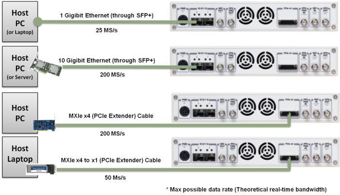
- Dual 10 Gigabit Ethernet - 200 MS/s Full Duplex @ 16-bit
- PCIe Express (Desktop) - 200 MS/s Full Duplex @ 16-bit
- ExpressCard (Laptop) - 50 MS/s Full Duplex @ 16-bit
- Dual 1 Gigabit Ethernet - 25 MS/s Full Duplex @ 16-bit
Front Panel
Rear Panel
Ref Clock - 10 MHz
Using an external 10 MHz reference clock, a square wave will offer the best phase noise performance, but a sinusoid is acceptable. The power level of the reference clock cannot exceed +15 dBm.
PPS - Pulse Per Second
Using a PPS signal for timestamp synchronization requires a square wave signal with the following a 5Vpp amplitude.
To test the PPS input, you can use the following tool from the UHD examples:
-
<args>are device address arguments (optional if only one USRP device is on your machine)
cd <install-path>/lib/uhd/examples ./test_pps_input –args=<args>
Front Panel GPIO
|
The GPIO port is not meant to drive big loads. You should not try to source more than 5mA per pin. The +3.3V is for ESD clamping purposes only and not designed to deliver high currents. |

|
Power on state
The hardware power on state and UHD initial state for the front-panel GPIOs is high-Z. For the X3xx, there are no external pull-ups/pull-downs for the GPIO pins, but the FPGAs do have them and they are configured as follows: X3xx: pull-down.
Pin Mapping
- Pin 1: +3.3V
- Pin 2: Data[0]
- Pin 3: Data[1]
- Pin 4: Data[2]
- Pin 5: Data[3]
- Pin 6: Data[4]
- Pin 7: Data[5]
- Pin 8: Data[6]
- Pin 9: Data[7]
- Pin 10: Data[8]
- Pin 11: Data[9]
- Pin 12: Data[10]
- Pin 13: Data[11]
- Pin 14: 0V
- Pin 15: 0V
Note: Please see the E3x0/X3x0 GPIO API for information on configuring and using the GPIO bus.
On-Board LEDs
| LED | Detail | Description |
|---|---|---|
| DS1 | 1.2V | power |
| DS2 | TXRX1 | Red: TX, Green: RX |
| DS3 | RX1 | Green: RX |
| DS4 | REF | reference lock |
| DS5 | PPS | flashes on edge |
| DS6 | GPS | GPS lock |
| DS7 | SFP0 | link |
| DS8 | SFP0 | link activity |
| DS10 | TXRX2 | Red: TX Green: RX |
| DS11 | RX2 | Green: RX |
| DS12 | 6V | daughterboard power |
| DS13 | 3.8V | power |
| DS14 | 3.3V | management power |
| DS15 | 3.3V | auxiliary management power |
| DS16 | 1.8V | FPGA power |
| DS16 | 3.3V | FPGA power |
| DS19 | SFP1 | link |
| DS20 | SFP1 | link active |
| DS21 | LINK | link activity |
Certifications
RoHS
As of December 1st, 2010 all Ettus Research products are RoHS compliant unless otherwise noted. More information can be found at http://ettus.com/legal/rohs-information
China RoHS
Management Methods for Controlling Pollution Caused by Electronic Information Products Regulation
Chinese Customers
National Instruments is in compliance with the Chinese policy on the Restriction of Hazardous Substances (RoHS) used in Electronic Information Products. For more information about the National Instruments China RoHS compliance, visit ni.com/environment/rohs_china.
Certificate of Volatility
X300/X310
Downloads
Choosing USRP X310 vs USRP X300
In terms of host bandwidth, interface options, and all other hardware features the USRP X300 and USRP 310 are identical. However, the USRP X310 provides a larger FPGA, a Xilinx XC7K410T, as opposed to XC7K325T. While both options provide a significant amount of free resources for custom FPGA development, the XC7K410T provides additional design margin, which translates to ease of development and future expandability. Most users choose the USRP X310 for their development.
| USRP X300 and X310 FPGA Resource Summary | ||
|---|---|---|
| Resource Type | USRP X300 (XC7K325T) | USRP X310 (XC7K410T) |
| Count | Count | |
| DSP48 Blocks | 840 | 1540 |
| Block Rams (18kB) | 890 | 1590 |
| Logic Cells | 326,080 | 406,720 |
| Slices (logic) | 50,950 | 63,550 |
For up-to-date information on FPGA resource utilization in the stock FPGA design, please see "USRP 300/X310 FPGA Resources" in the Ettus Research knowledge base (https://kb.ettus.com).
Choosing an RF Daughterboard
With the increased sample rates used by the USRP X300 and USRP X310, these new device can support extended-bandwidth daughterboards. The WBX-120, SBX-120, and CBX-120 are recommended to take advantage of the full bandwidth capability of the USRP X300 and X310. The WBX-120, SBX-120, and CBX-120 have been upgraded from their predecessors (40 MHz) to use 120 MHz baseband filters. You can select your daughterboard based on the center frequency of your primary application.
| Daughterboard | Frequency Range | Bandwidth |
|---|---|---|
| WBX-120 | 50 MHz - 2200 MHz | 120 MHz |
| SBX-120 | 400 MHz - 4400 MHz | 120 MHz |
| CBX-120 | 1200 MHz - 6000 MHz | 120 MHz |
| UBX-160 | 10 MHz - 6000 MHz | 160 MHz |
| TwinRX | 10 MHz - 6000 MHz | 80 MHz per channel, 160 MHz total |
If your application is in the HF frequency range, the LFRX and LFTX are recommended for up to 30 MHz of bandwidth per channel. The BasicRX and BasicTX are ideal for configurations that use an external frontend for tuning and filtering with either an IF or baseband interface.
The USRP X300 and X310 are backward compatible with legacy daughterboards except for the RFX Series and XCVR2450. Please note, while there are two daughterboard slots, the USRP X300/X310 can only support a single TVRX2.
If you plan to transmit or receive over the air, you should also purchase an antenna.
Choosing a Host Interface
The USRP X300/X310 provide three interface options – 1 Gigabit Ethernet (1 GigE), 10 Gigabit Ethernet (10 GigE), and PCI-Express (PCIe). Generally, Ettus Research recommends using 10 GigE to achieve the maximum throughput available from the USRP X300/X310. PCIe is recommended for applications that require the lowest possible latency, which is a desirable characteristic for PHY/MAC research. If your application does not require the full bandwidth of the USRP ™ X300 and X310, the 1 GigE interface serves as a cost-effective fall-back option. Ettus Research provides a complete interface kit for each of these options, which is also shown in Table 3.
| Table 3 - Interface Performance Summary | |||
|---|---|---|---|
| Interface | Throughput (MS/s @ 16-bit) | Target | Recommended Kit |
| 1 Gigabit | 25 MS/s | Desktop/Laptop | Components provided with USRP X300/X310 kit.
For additional connections, purchase the following: SFP Adapter + GigE Cable |
| 10 Gigabit | 200 MS/s | Desktop | 10 GigE Interface Kit |
| PCI-Express
(PCIe, 4 lane) |
200 MS/S | Desktop | PCI-Express Desktop Kit |
| Express Card
(PCIe, 1 lane) |
50 MS/s | Laptop | ExpressCard Kit |
10 Gigabit Ethernet
In order to utilize the X-series USRP over dual 10 Gigabit Ethernet interfaces, ensure either the XG image is installed (see FPGA Image Flavors). In addition to burning the prerequisite FPGA image, it may also be necessary to tune the network interface card (NIC) to eliminate drops (Ds) and reduce overflows (Os). This is done by increasing the number of RX descriptors (see Linux specific notes).
The benchmark_rate tool can be used to test this capability. Run the following commands to test the X-series USRP over both 10 Gigabit Ethernet interfaces with the maximum rate of 200 Msps per channel:
   cd <install-path>/lib/uhd/examples
   ./benchmark_rate --args="type=x300,addr=<Primary IP>,second_addr=<secondary IP>" --channels="0,1" --rx_rate 200e6
The second interface is specified by the extra argument second_addr.
Recommended 10 Gigabit Ethernet Cards
- Intel X520-DA2 - Previous generation PCIe Gen 2 adapter. Mature and stable 10GbE adapter, works out-of-the-box with Ubuntu 14.04 LTS and 16.04 LTS
- Intel X520-DA1 - Previous generation PCIe Gen 2 adapter Mature and stable 10GbE adapter, works out-of-the-box with Ubuntu 14.04 LTS and 16.04 LTS
- Intel X710-DA2 - New PCIe Gen 3 adapter
- Intel X710-DA4 - New PCIe Gen 3 adapter
Additional Links and Resources for Intel 10GbE adapters
International Power Supply Options
The power supply provided with the USRP X300/X310 kit is packaged with a power cord that is compatible with power outlets in the US/Japan. If you are not using the USRP X300/X310 in the US/Japan, we recommend purchasing the International USRP X300/X310 Power Cord set.
Option: GPS Disciplined, Oven-Controlled Oscillator (GPSDO)
The USRP X300 and USRP X310 provide the option to integrate a high-accuracy GPS-disciplined oscillator (GPSDO). The GPSDO improves the accuracy of the internal frequency reference to 20 ppb, or 0.1 ppb if the GPS is synchronized to the GPS constellation. When synchronized to the GPS constellation, all USRP ™ devices will also be synchronized in time within 50 ns.
| Internal TCXO | GPS-Disciplined Clock | |
|---|---|---|
| Frequency Reference | TCXO | OCXO |
| Frequency Accuracy | ± 2.5ppm
± 2,500 Hz @ 1 GHz |
± 20 ppb
± 20 Hz @ 1 GHz |
| Frequency Accuracy | ± 0.01ppb | |
| (GPS-Disciplined) | ~ ± 0.01 Hz @ 1 GHz | |
| GPS Time Sync Accuracy | ±50ns to UTC Time** | |
| 10 MHz Reference Phase Drift with GPS Sync | <±20ns After 1 Hour** |
Option: Antenna Kit for GPSDO
The GPSDO Mini Kit will improve the accuracy of the USRP reference clock, even if it does not receive signals from the GPS Constellation. However, to achieve the best accuracy possible, and to achieve global timing alignment across multiple USRPs, Ettus Research recommends the GPSDO Mini Antenna Kit.
Option: General Purpose Input/Output (GPIO) Kit
The USRP X300 and X310 include a DB15 connector on the front panel that provides convenient access to GPIO signals. Each pin can be configured as an input or output, uses 3.3V-level logic, and is protected with basic anti-static circuitry. These pins can be used to control external devices like RF switches and amplifiers, trigger software events on the host, or even provide basic debugging functionality. The USRP GPIO Kit is an affordable option that provides access to these signals with a DB15 cable and a breakout board. The breakout board allows the user to connect external devices through a terminal block. The user can also solder wires and components into the dedicated prototyping area.
Option: Cables for MIMO Expansion
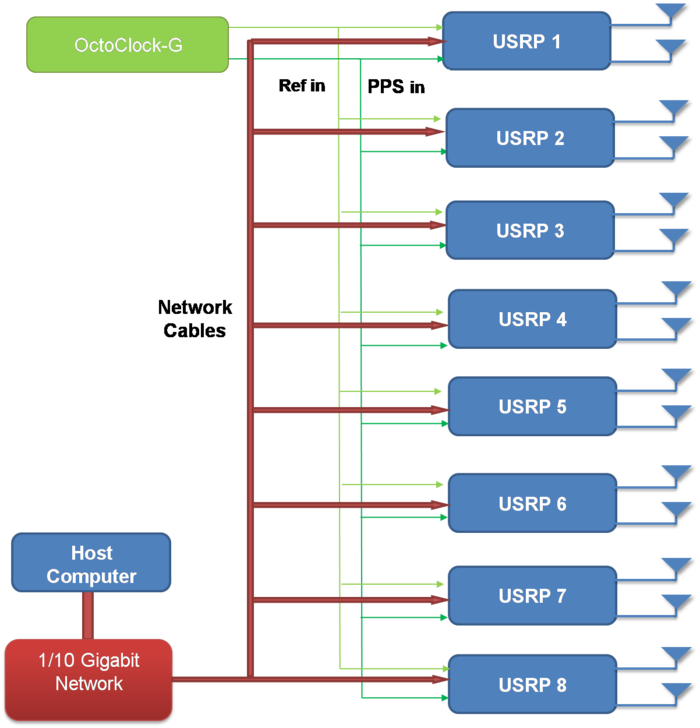
Multiple USRP X300/X310s can be synchronized for coherent operation by sharing a common 10 MHz and 1 PPS signal. We recommend using a star-distribution topology with an OctoClock or OctoClock-G, as seen in Figure 4. This requires matched length cables to be used for both 10 MHz and 1 PPS.
For more information about MIMO operation, please see the MIMO and Synchronization Application Note.
Option: USRP X300/X310 Rackmount
The USRP X300/X310 was designed to use a convenient half-wide 1U rack-mount form factor. This allows developers to build high-density MIMO systems in a neat and well organized setup. If the user will be developing in a lab environment, or building a high-channel count system, the 1U Rackmount Assembly is recommended. However, if the user plans to work with the USRP X300/X310 on a desk, the rackmount is not required. Rubber standoffs are mounted on the USRP X300/X310 to avoid direct contact and surface scratching.
Guidance on SFP+ Adapters for Fiber Connectivity on USRP X300/X310
Ettus Research currently offers direct-connect, copper cabling accessories for the USRP X300 and USRP X310. However, it is also possible to use multi-mode fiber instead of copper connections for these devices. In this document, we will provide general guidance on the types of fiber adapters and cables that can be used with these products. General Guidance on SFP+ Adapters
The USRP X Series is compatible with most brands of SFP+ fiber adapters. In some cases, other equipment in the systems such as 1/10 Gigabith Ethernet switches are only compatible with specific brands of SFP+ adapters and cables. As a general rule, we recommend checking compatibility with the switches and network cards in your system before purchasing an adapter.
Ettus Research does test the USRP X Series devices with our 10 Gigabit Ethernet Connectivity Kit and a Blade Networks G8124 1/10 GigE switch. Here are is a list of known-good cables and adapters.
Ettus Research has only tested multi-mode fiber accessories.
Known-Good Adapters
Known-Good Cables
FAQ
USRP™ X300 and USRP™ X310 SDRs Frequently Asked Questions
- What is the bandwidth of the USRP X300/X310
The ADC rate on each analog RX channel is 200 MS/s quadrature, which provides a theoretical analog bandwidth of approximately 80% of the Nyquist bandwidth of +/- 100 MHz (+/- 80 MHz around the center frequency). The resulting maximum theoretical analog bandwidth is 160 MHz. The actual analog bandwidth may be reduced due the RF daughterboard selected.
RF Daughterboard Bandwidths: See the daughterboard specifications [link]
FPGA Processing Bandwidth: Up to 200 MS/s quadrature.
Host Bandwidth: Up to 200 MS/s quadrature, dependent on selected interface
For more information about achieving the maximum bandwidth with a USRP X300/X310, please see the "USRP X300/X310 Configuration Guide" or the "USRP System Bandwidth" application note.
- How can I program the USRP X300/X310
Like all other USRP models, the USRP X300 and X310 are compatible with the USRP Hardware Driver™ (UHD) architecture. The UHD architecture is a common driver that allows users to develop and execute applications on a host-PC. UHD provides a direct C++ API to control and stream to/from the USRP X300/X310. It also provides compatibility with a variety of third-party software frameworks including GNU Radio, LabVIEW, and Matlab. You may also customize the FPGA image provided with UHD to integrate your own signal processing. For more information about UHD, and supported software frameworks, please see:
http://files.ettus.com/manual/
- How do I update the FPGA images and firmware with the latest from UHD
You can find more information about updating the FPGA image through PCIe, 1/10 GigE, and JTAG here.
- How can I modify the FPGA of the USRP X300/X310
The source code (Verilog) for the USRP X300/X310 is available in the UHD repository. The USRP X300/X310 requires ISE 14.4 or newer. The build process leverages the existing CMAKE build system used to compile the host-side driver. A Linux-based setup will provide the best results.
- How much free space is available in the USRP X300/X310 FPGA
Please see the USRP X300/X310 FPGA resources page for more information.
- What type of PC setup is recommended for use with the USRP X300/X310
The type of PC required depends heavily on the complexity and bandwidth of the application. To demonstrate the USRP X300/X310, we typically use a desktop computer with a quadcore i7, 8+ GB of DDR3, and install the PCIe interface card that is also provide with the 10 GigE, PCIe, and ExpressCard interface kits.
- What frequency range does the USRP X300/X310 cover
The frequency range depends on the daughterboard select by the users. For more information, please see the USRP X300/X310 Configuration Guide.
- What components do I need to purchase for a complete USRP X300/X310 system
For a more comprehensive guide, please see the USRP X300/X310 Configuration Guide.
- What is the difference between the USRP X300/X310
The USRP X310 includes a larger Kintex-7 series FPGA (XC7K410T) with additional development resources for more complex designs. The USRP X300 includes the smaller XC7K325T FPGA.


