USRP N320/N321 LO Distribution
Contents
Application Note Number
AN-725
Revision History
| Date | Author | Details |
|---|---|---|
| 2019-04-17 | Brian Avenell | Initial creation |
Introduction
In applications requiring multiple transmitters or receivers tuned to the same frequency, a further requirement may be to have the LOs phase synchronous. In systems with phase synchronous LOs, the LOs, and as a result, the channels themselves, have deterministic phase. This deterministic phase holds when retuning the LOs. Achieving deterministic phase can either be accomplished by using LO synthesizers that accept a sync pulse in order to set their phase after retuning or by sharing the LOs between the individual channels. Sharing the LO results in more immunity to channel-to-channel relative phase drift versus temperature.
The USRP N320/N321 transceivers utilize a LO sharing mechanism. In particular, the LO distribution uses a star configuration which allows for higher channel count over daisy-chain configurations. Solutions up to 128x128 channels can be configured. This application note provides connection instructions and UHD programming instructions for the various LO distribution configurations.
Block Diagram Overview
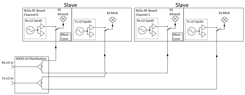
Figure 1 contains the block diagram highlighting the LO distribution for the USRP N320
Each channel contains an internal LO for both the Rx and Tx paths which enables tuning when the USRP N320 is operating as a stand alone module. When configured in a phase synchronous system where a single LO is shared between several modules, the internal LOs are bypassed to allow importing an external LO. The LO Distribution is a passive splitter that routes a single LO from front panel to be routed to each of the two channels. Separate LOs exist for Tx and Rx to allow independent tuning of these paths.
Figure 2 shows the N320 front panel with the LO inputs highlighted.
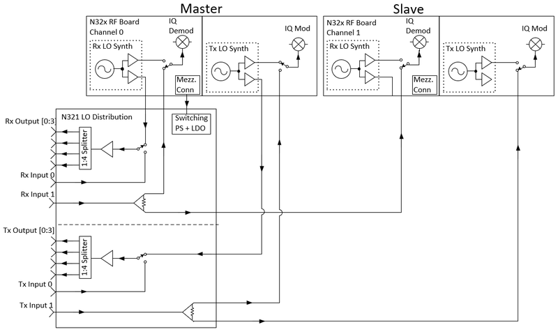
Figure 3 shows the block diagram of the N321 module with the LO distribution section included.
Channel 0 provides the LO for both the Tx and Rx paths. The LO distribution board contains identical circuitry for both the Rx and Tx paths. The channel 0 LO is routed from the RF board to the 1:4 power splitter in the LO distribution board. LO Input 0 is used for downstream modules where the LO signal is routed to the 1:4 splitter. For LO Input 1, the LO routes to the RF board. The N321 front panel with the LO ports highlighted is shown in Figure 4
UHD LO Distribution Commands
Commands related to LO Distribution are part of the multi_usrp objects within UHD.
RF board LOs set to accept an external LO Tx path:
set_tx_lo_source(“external”, “lo1”, channel)
Rx path:
set_rx_lo_source(“external”, “lo1”, channel)
where channel = 0 | 1
Routing RF Board’s LO to the LO Distribution board’s 1:4 splitter. This only applies to the Master LO.
Tx path:
set_tx_lo_export_enabled(true, “lo1”, 0)
Rx path:
set_rx_lo_export_enabled(true, “lo1”, 0)
Route LO from front panel IN0 port to the 1:4 splitter Tx path:
set_tx_lo_export_enabled(false, “lo1”, 0)
Rx path:
set_rx_lo_export_enabled(false, “lo1”, 0)
Enable Distribution Output Ports Tx path:
get_device()->get_tree()->access<bool>("mboards/0/dboards/A/tx_frontends/0/los/lo1/lo_distribution/LO_OUT_<output_number>/export").set(<output_enabled>)
Rx path:
get_device()->get_tree()->access<bool>("mboards/0/dboards/A/rx_frontends/0/los/lo1/lo_distribution/LO_OUT_<output_number>/export").set(<output_enabled>)
   <output_number> = 0 |1|2|3
   <output_enabled> = true | false
N321 + N320 Cabling Diagram
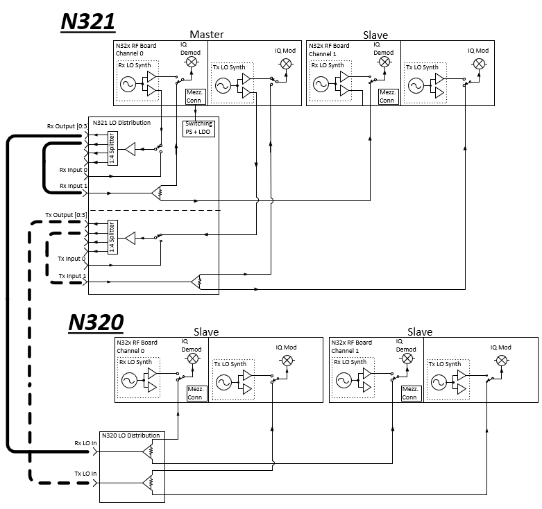
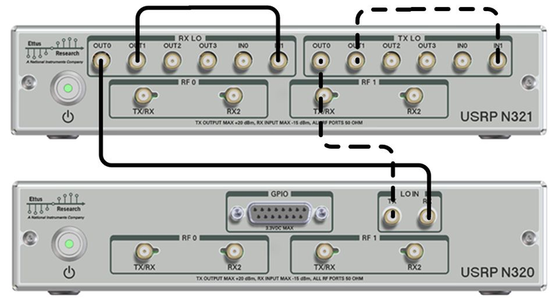
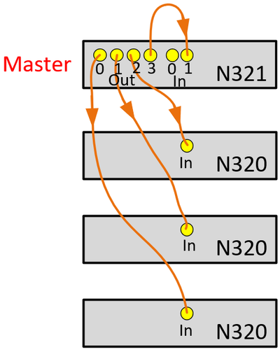
For a 4x4 channel configuration the block diagram cabling diagram is depicted in Figure 5 and Figure 6. For lowest phase drift performance it is best to ensure that the cable lengths are similar.
In this use case, the following UHD configuration is required:
N321 configuration:
   set_tx_lo_source(“external”, “lo1”, 0)
   set_tx_lo_source(“external”, “lo1”, 1)
   set_rx_lo_source(“external”, “lo1”, 0)
   set_rx_lo_source(“external”, “lo1”, 1)
   set_tx_lo_export_enabled(true, “lo1”, 0)
   set_rx_lo_export_enabled(true, “lo1”, 0)
   get_device()->get_tree()->access<bool>("mboards/0/dboards/A/tx_frontends/0/los/lo1/lo_distribution/LO_OUT_0/export").set(true)
   get_device()->get_tree()->access<bool>("mboards/0/dboards/A/tx_frontends/0/los/lo1/lo_distribution/LO_OUT_1/export").set(true)
   get_device()->get_tree()->access<bool>("mboards/0/dboards/A/rx_frontends/0/los/lo1/lo_distribution/LO_OUT_0/export").set(true)
   get_device()->get_tree()->access<bool>("mboards/0/dboards/A/rx_frontends/0/los/lo1/lo_distribution/LO_OUT_1/export").set(true)
N320 configuration:
   set_tx_lo_source(“external”, “lo1”, 0)
   set_tx_lo_source(“external”, “lo1”, 1)
   set_rx_lo_source(“external”, “lo1”, 0)
   set_rx_lo_source(“external”, “lo1”, 1)
Cabling for Higher Channel Count
Figure 7 shows a simplified cabling diagram for up to 8x8 shared channels:
For simplicity, only Rx LO routing is shown. Tx routing would be identical. The color coding on the cables indicates similar length cabling.
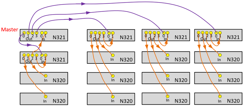
Between 9x9 and 32x32 channels, use the cabling configuration shown in Figure 8.
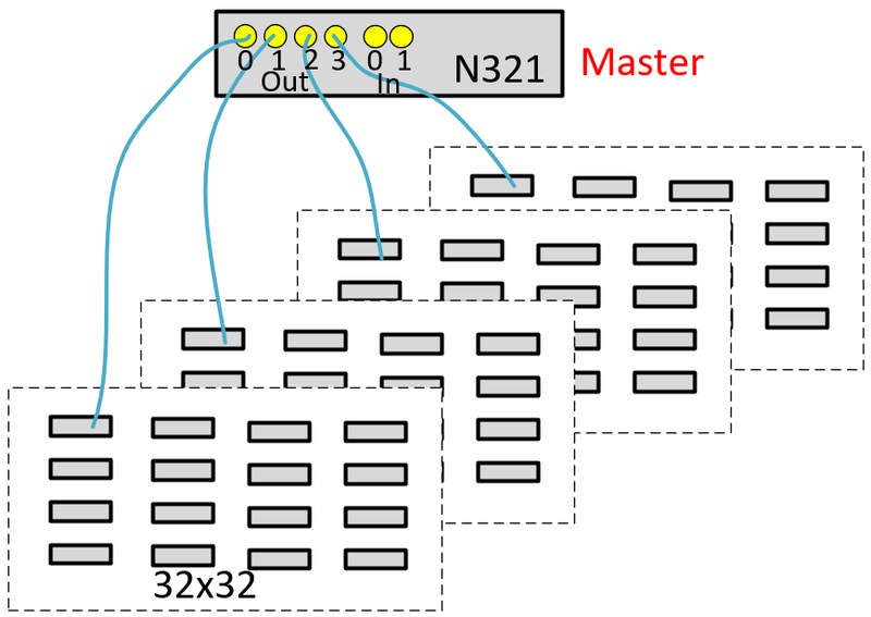
Between 33x33 and 128x128 channels, use the cabling configuration shown in Figure 9.
Each tile of 32x32 channels in Figure 9 use the cabling shown in Figure 8. The N321 labelled as Master provides the LO to each of the 32x32 tiles. The Master N321 only provides the LO signals, Rx and Tx portions of this module are not used. In each tile the Master LO is routed to the tiles N321 In0 port.
Measured Performance
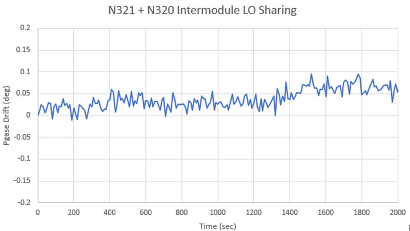
Figure 10 shows the phase drift between two channels, these channels located in separate modules, at ambient temperature of 25 deg C.
Phase drift is less than 0.1 degrees.
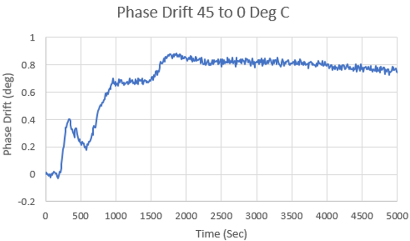
Figure 11 shows the phase drift between two channels when the ambient temperature is changed from 45 deg C to 0 deg C.
Phase drift is less than 0.9 degrees.
Summary
LO sharing in a star configuration provides highly stable phase coherency for multi-channel applications. MIMO and direction finding are two examples that require multi-channel with phase coherency. The USRP N320/N321 has a highly configurable LO sharing topology that allows up to 128 shared channels for both Rx and Tx.

