X300/X310 Device Recovery
Contents
Application Note Number and Authors
AN-305
Nate Temple and Michael Dickens
Overview
This application note covers the process of recovering the USRP X300/X310 by flashing the FPGA image via the JTAG interface.
Note: This guide is written for Linux only. In theory it can be made to work on any OS that supports Xilinx Vivado.
Manual
For reference, please refer to the user manual page for the X300/X310.
Required Tools
- Host Computer
- - USB2/3 port
- - 1 GbE or 10 GbE network interface (NIC)
- - Supports Xilinx Vivado Lab installation
- - Supports UHD installation
- Connections from host to the X3x0 USRP via
- - USB2 cable
- - One of the following, depending on the host computer's NIC
- SFP+ / RJ45 Adapter and Ethernet cable
- SFP+ DAC cable
Prerequisites
This guide assumes you have a Linux-based host computer that supports Xilinx Vivado, with UHD installed into the default prefix /usr/local; for example we are using Ubuntu Linux and installed UHD from source using the default CMAKE_INSTALL_PREFIX. If you do not have UHD installed, please install it, for example via the Building and Installing the USRP Open-Source Toolchain (UHD and GNU Radio) on Linux Application Note.
We recommend using an X310 FPGA image provided by the host computer's UHD install, so that their versions match up. During runtime, UHD checks its version against that of all target USRPs' FPGA versions, and if they are too different then UHD prints an note about the mismatch and errors out.
There are circumstances where using different versions for the host UHD and FPGA image is necessary; performing this scenario is very similar to the steps in this guide, but requires some additional steps once the USRP is accessible via networking. We do not cover this scenario in this guide. If you need assistance under this scenario, please contact Ettus Support for assistance and we will provide you with the extra note steps.
If you do not have the FPGA images downloaded for your current host UHD install, you can obtain them by executing the command:
sudo uhd_images_downloader
Verify you have the FPGA images downloaded by running the command:
ls -alh /usr/local/share/uhd/images/usrp_x3*
Installing Xilinx Vivado Lab Edition
You will need to have an install of Xilinx Vivado Lab Edition, Xilinx Vivado Design Edition, or Xilinx Vivado System Edition. If you have none of those installed, then the minimum install is via Xilinx Vivado Lab Edition -- and that's what we cover in this guide. If you are using the Xilinx Vivado Design or System Edition then the paths may differ slightly from those described herein but the basic steps and process are the same; you can skip this section and go to the next one.
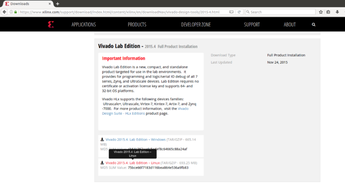
Xilinx Vivado Lab Edition can be downloaded from one the following links:
For this application note, we use an older Ubuntu and thus older Xilinx Vivado Lab Edition: 2015.4. Regardless of the version of Xilinx Vivado you use, the steps below are roughly the same.
After the download is complete, you can verify the MD5 sum of the file if you choose to do so, since Xilinx provides a MD5 SUM Value for each download:
   cd ~/Downloads
   md5sum Xilinx_Vivado_Lab_Lin_2015.4_1118_2.tar.gz
Note: The filename and MD5 hash may differ from the screen capture shown. Verify the MD5 sum against the hash listed on the Xilinx download page.
Next, decompress the downloaded tarball:
tar -zxvf Xilinx_Vivado_Lab_Lin_2015.4_1118_2.tar.gz
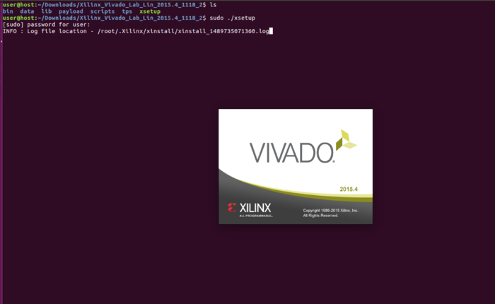
Next, go into the new directory and run the xsetup installer using superuser sudo permissions:
   cd Xilinx_Vivado_Lab_Lin_2015.4_1118_2
   sudo ./xsetup
This will launch the Xilinx Vivado Lab installer.
You might be prompted that you are running OS that is not yet officially supported, for example using Ubuntu 20.04 with Xilinx Vivado Lab 2019.1. We generally do not recommend running an older Vivado on a more recent OS, though it might work; proceed at your own comfort level! In this situation, we generally recommend you instead use a more recent Xilinx Vivado Lab release, or use a slightly older OS version -- for example via a virtual machine (VM).
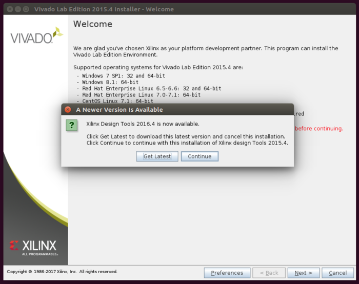
You might be prompted that a newer version is available; if so ignore this popup and click Continue.
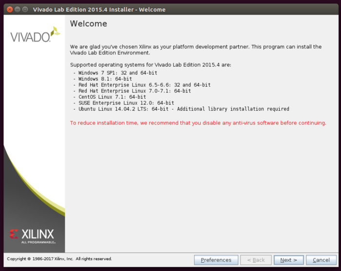
The installer will then be at a Welcome screen, click Next.
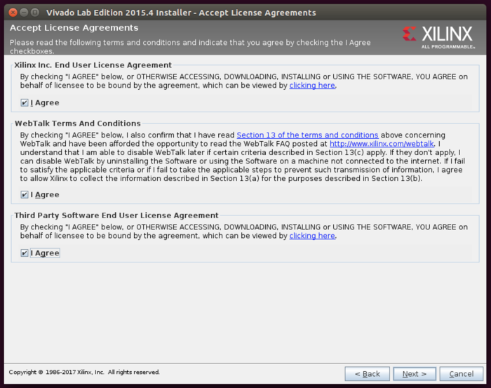
You will then be prompted to accept the various License Agreements, select all of the "I Agree" boxes then click Next.
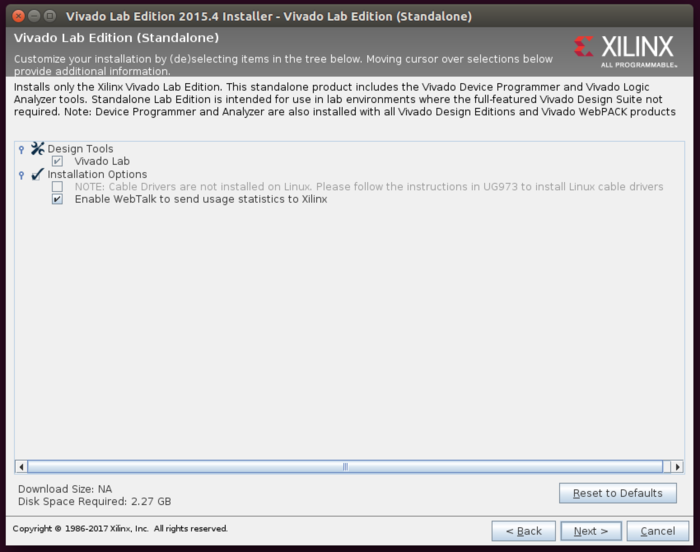
You will then be prompted to select the install options. It is suggested to leave the default values, click Next.
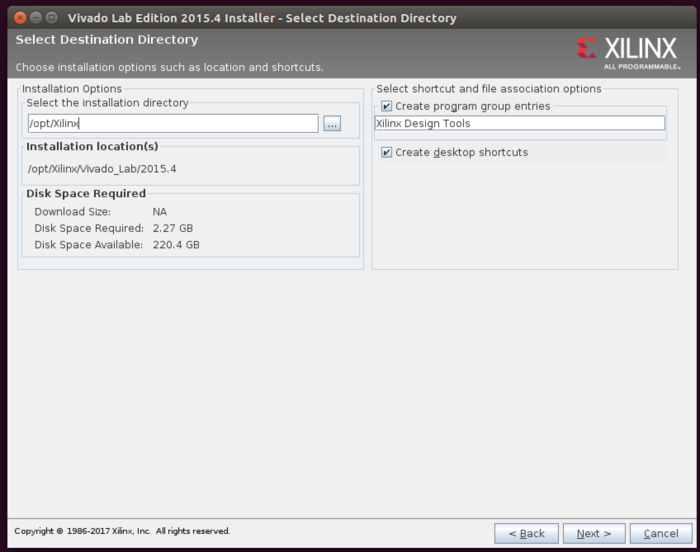
You will then be prompted with the installation locations. The default value for older Xilinx Vivado Lab is /opt/Xilinx while for newer versions it is /tools/Xilinx. We will be using the former here; what you use is your choice, but please note the install directory so that you can make sure to use it correctly later in this guide.
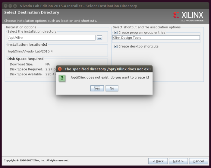
If the install directory does not exist, you will be prompted immediately to create it. Click Yes.
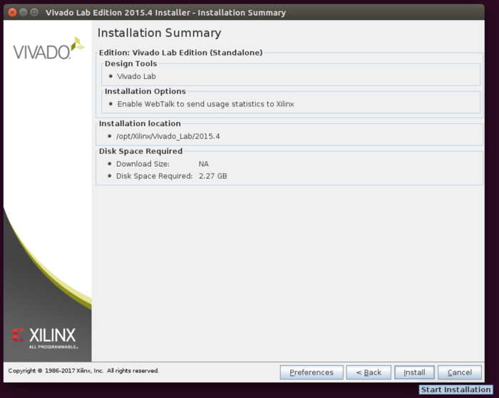
Finally, you will be at the Installation Summary prompt. Click Install.
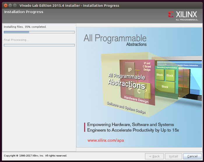
The installer has to download files from the internet, but they are not large and hence the installation process typically takes only a few minute.
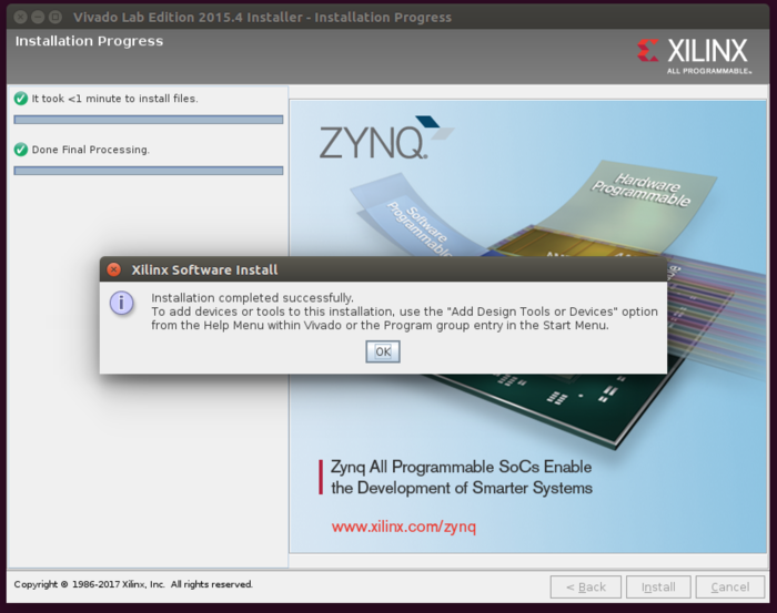
You will then be prompted that the installation was successful. Click Ok, and the installer will close.
Installing the Digilent Cable Driver
In order to use the JTAG interface built into the USRP X300/X310 front panel, you will need to install the Digilent Cable Driver. It is included with the Xilinx Vivado Lab Edition package.
Navigate to the folder /opt/Xilinx/Vivado_Lab/2015.4/data/xicom/cable_drivers/lin64/install_script/install_drivers, and run the installer script.
   cd /opt/Xilinx/Vivado_Lab/2015.4/data/xicom/cable_drivers/lin64/install_script/install_drivers
   sudo ./install_digilent.sh
Next, reload the UDEV rules
sudo udevadm control --reload
Configuring Network Interface
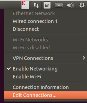
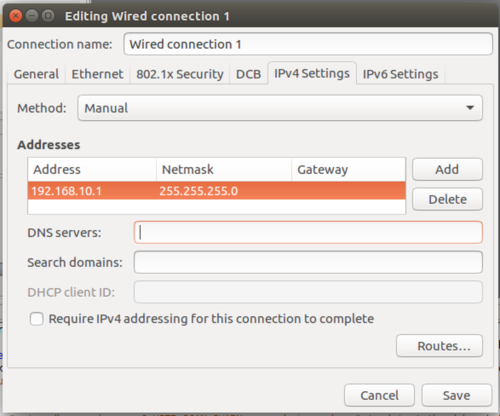
You will need to set your ethernet interface that will be connected to the USRP X300/X310 to a static IP address of 192.168.10.1 along with setting a MTU of 1500.
Connect the X300/X310
Connect the USRP X300/X310 with the USB2 cable via the JTAG port on the front face plate. You can also attach the SFP+/RJ45 adapter to Port 0 and connect your computer via ethernet.
Power on the USRP X300/X310.
Starting Xilinx Vivado Lab Edition
Start by navigating back to your home directory:
cd ~/
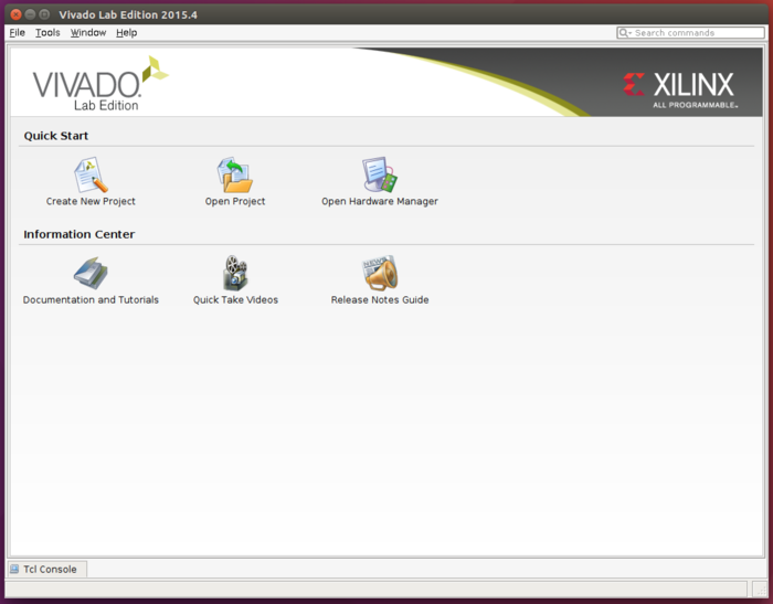
Next, start Xilinx Vivado Lab
/opt/Xilinx/Vivado_Lab/2015.4/bin/vivado_lab
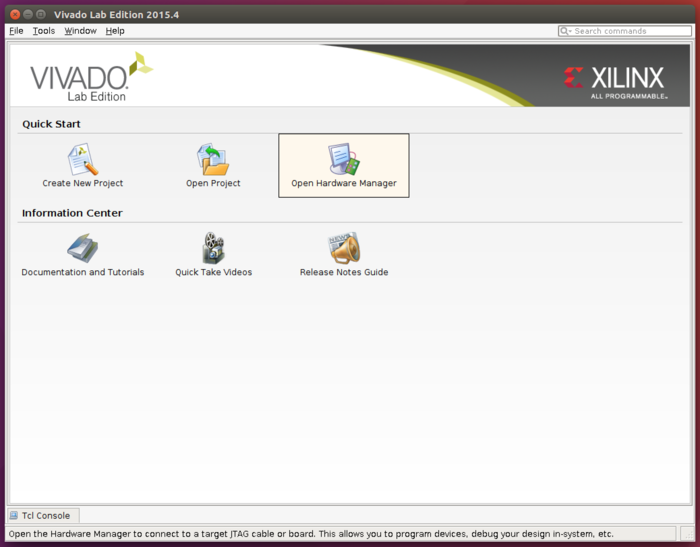
Open the Hardware Manager
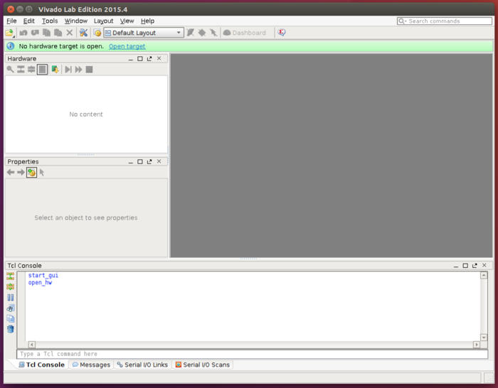
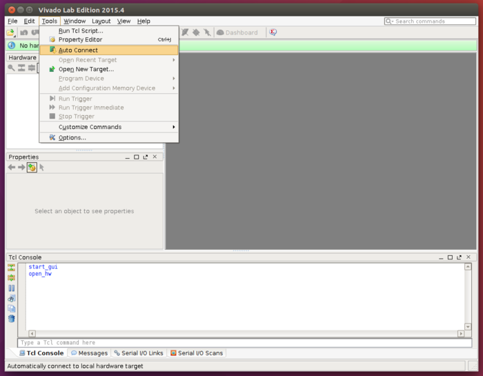
Next, within the menu the of the Hardware Manager select Tools -> Auto Connect.
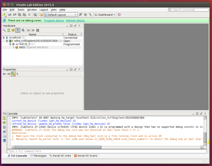
The details of the FPGA should populate the window on the left side of the Hardware Manager.
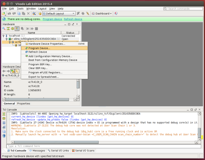
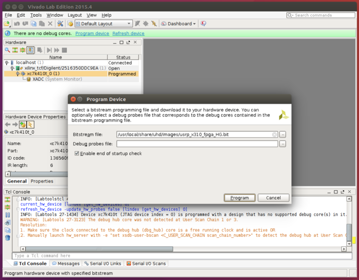
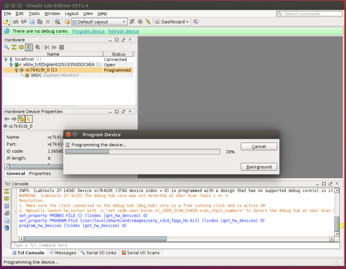
Right click on the FPGA listed, and select Program Device.
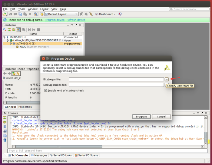
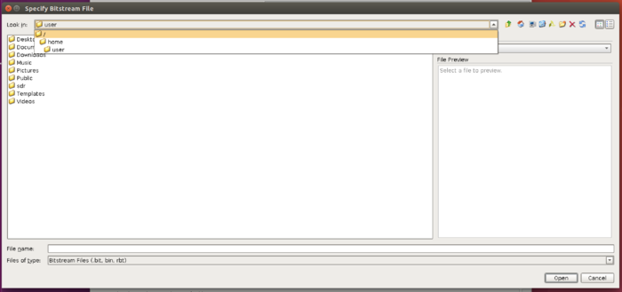
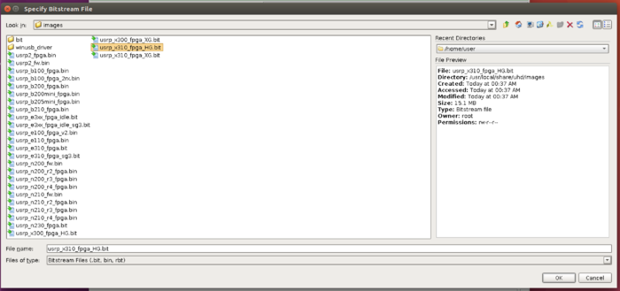
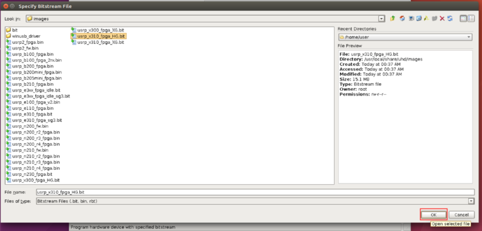
This will popup a new window. Click on the file selection button and navigate to the location of the UHD FPGA images, and select the correct FPGA image for your device. (/usr/local/share/uhd/images)
Note: Select the correct FPGA image that matches your USRP (either _x300 or _x310) with the .bit file extension. It is recommended to select the _HG FPGA image, which will initialize Port 0 as 1 GbE and Port 1 as 10 GbE. Advanced users operating with dual 10 GbE may select the _XG image, however you will need to adjust the instructions listed within this document to match the dual 10GbE configuration (IP Addresses, MTU settings, etc).
Next, click Program.
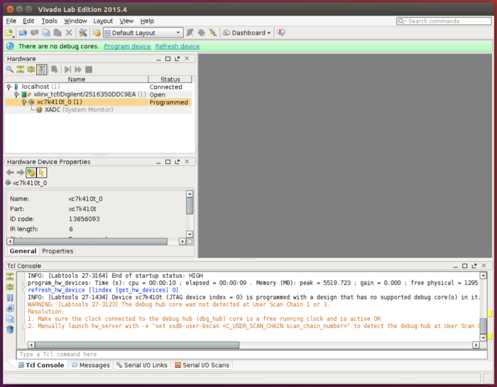
A progress bar will popup as the FPGA is programmed.
Once the programming is completed, close Vivado Lab.
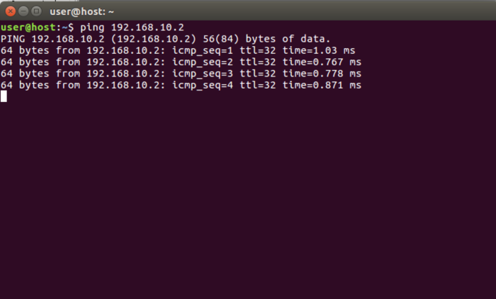
Return to a terminal and attempt to ping the USRP X300/X310.
ping 192.168.10.2
Stop the ping with CTRL-C.
At this point, if you're able to ping the USRP X300/X310, attempt to run the UHD utility uhd_usrp_probe.
uhd_usrp_probe
Example output from uhd_usrp_probe:
user@host:~$ uhd_usrp_probe
linux; GNU C++ version 5.4.0 20160609; Boost_105800; UHD_003.010.001.HEAD-0-gc705922a

-- X300 initialization sequence...
-- Determining maximum frame size... 1472 bytes.
-- Setup basic communication...
-- Loading values from EEPROM...
-- Setup RF frontend clocking...
-- Radio 1x clock:200
-- [DMA FIFO] Running BIST for FIFO 0... pass (Throughput: 1304.3MB/s)
-- [DMA FIFO] Running BIST for FIFO 1... pass (Throughput: 1300.5MB/s)
-- [RFNoC Radio] Performing register loopback test... pass
-- [RFNoC Radio] Performing register loopback test... pass
-- [RFNoC Radio] Performing register loopback test... pass
-- [RFNoC Radio] Performing register loopback test... pass
-- Performing timer loopback test... pass
-- Performing timer loopback test... pass
  _____________________________________________________
 /
|       Device: X-Series Device
|     _____________________________________________________
|    /
|   |       Mboard: X310
|   |   revision: 8
|   |   revision_compat: 7
|   |   product: 30818
|   |   mac-addr0: 00:00:00:00:00:00
|   |   mac-addr1: 00:00:00:00:00:00
|   |   gateway: 192.168.10.1
|   |   ip-addr0: 192.168.10.2
|   |   subnet0: 255.255.255.0
|   |   ip-addr1: 192.168.20.2
|   |   subnet1: 255.255.255.0
|   |   ip-addr2: 192.168.30.2
|   |   subnet2: 255.255.255.0
|   |   ip-addr3: 192.168.40.2
|   |   subnet3: 255.255.255.0
|   |   serial: xxxxxxxx
|   |   FW Version: 5.1
|   |   FPGA Version: 33.0
|   |   RFNoC capable: Yes
|   |
|   |   Time sources:  internal, external, gpsdo
|   |   Clock sources: internal, external, gpsdo
|   |   Sensors: ref_locked
|   |     _____________________________________________________
|   |    /
|   |   |       RX Dboard: A
|   |   |   ID: UBX-160 v1 (0x007a)
|   |   |   Serial: xxxxxxxx
|   |   |     _____________________________________________________
|   |   |    /
|   |   |   |       RX Frontend: 0
|   |   |   |   Name: UBX RX
|   |   |   |   Antennas: TX/RX, RX2, CAL
|   |   |   |   Sensors: lo_locked
|   |   |   |   Freq range: 10.000 to 6000.000 MHz
|   |   |   |   Gain range PGA0: 0.0 to 31.5 step 0.5 dB
|   |   |   |   Bandwidth range: 160000000.0 to 160000000.0 step 0.0 Hz
|   |   |   |   Connection Type: IQ
|   |   |   |   Uses LO offset: No
|   |   |     _____________________________________________________
|   |   |    /
|   |   |   |       RX Codec: A
|   |   |   |   Name: ads62p48
|   |   |   |   Gain range digital: 0.0 to 6.0 step 0.5 dB
|   |     _____________________________________________________
|   |    /
|   |   |       RX Dboard: B
|   |   |     _____________________________________________________
|   |   |    /
|   |   |   |       RX Frontend: 0
|   |   |   |   Name: Unknown (0xffff) - 0
|   |   |   |   Antennas:
|   |   |   |   Sensors:
|   |   |   |   Freq range: 0.000 to 0.000 MHz
|   |   |   |   Gain Elements: None
|   |   |   |   Bandwidth range: 0.0 to 0.0 step 0.0 Hz
|   |   |   |   Connection Type: IQ
|   |   |   |   Uses LO offset: No
|   |   |     _____________________________________________________
|   |   |    /
|   |   |   |       RX Codec: B
|   |   |   |   Name: ads62p48
|   |   |   |   Gain range digital: 0.0 to 6.0 step 0.5 dB
|   |     _____________________________________________________
|   |    /
|   |   |       TX Dboard: A
|   |   |   ID: UBX-160 v1 (0x0079)
|   |   |   Serial: xxxxxxxx
|   |   |     _____________________________________________________
|   |   |    /
|   |   |   |       TX Frontend: 0
|   |   |   |   Name: UBX TX
|   |   |   |   Antennas: TX/RX, CAL
|   |   |   |   Sensors: lo_locked
|   |   |   |   Freq range: 10.000 to 6000.000 MHz
|   |   |   |   Gain range PGA0: 0.0 to 31.5 step 0.5 dB
|   |   |   |   Bandwidth range: 160000000.0 to 160000000.0 step 0.0 Hz
|   |   |   |   Connection Type: QI
|   |   |   |   Uses LO offset: No
|   |   |     _____________________________________________________
|   |   |    /
|   |   |   |       TX Codec: A
|   |   |   |   Name: ad9146
|   |   |   |   Gain Elements: None
|   |     _____________________________________________________
|   |    /
|   |   |       TX Dboard: B
|   |   |     _____________________________________________________
|   |   |    /
|   |   |   |       TX Frontend: 0
|   |   |   |   Name: Unknown (0xffff) - 0
|   |   |   |   Antennas:
|   |   |   |   Sensors:
|   |   |   |   Freq range: 0.000 to 0.000 MHz
|   |   |   |   Gain Elements: None
|   |   |   |   Bandwidth range: 0.0 to 0.0 step 0.0 Hz
|   |   |   |   Connection Type: IQ
|   |   |   |   Uses LO offset: No
|   |   |     _____________________________________________________
|   |   |    /
|   |   |   |       TX Codec: B
|   |   |   |   Name: ad9146
|   |   |   |   Gain Elements: None
|   |     _____________________________________________________
|   |    /
|   |   |       RFNoC blocks on this device:
|   |   |
|   |   |   * DmaFIFO_0
|   |   |   * Radio_0
|   |   |   * Radio_1
|   |   |   * DDC_0
|   |   |   * DDC_1
|   |   |   * DUC_0
|   |   |   * DUC_1
If running uhd_usrp_probe is successful, proceed with flashing the FPGA image with the UHD utility uhd_image_loader.
Note: Flashing the FPGA image via JTAG only does not write the FPGA image to EEPROM, you must run the uhd_image_loader to write the FPGA image to the internal EEPROM.
uhd_image_loader --args "type=x300,addr=192.168.10.2,fpga=HG"
When uhd_image_loader has completed the flashing process, it will recommend to power cycle the USRP X300/X310.
Power off the USRP X300/X310, remove the JTAG USB cable, and then power on the USRP X300/X310.
The USRP X300/X310 is now recovered. You should be able to ping, run uhd_usrp_probe and any other UHD utility/application as normal.


