Difference between revisions of "Open Architecture For Radar and EW Research"
(fix internal link for LO distribution) |
(Redirected page to Multichannel RF Reference Architecture) |
||
| (24 intermediate revisions by 2 users not shown) | |||
| Line 1: | Line 1: | ||
| − | ==Application Note Number and | + | #REDIRECT [[Multichannel RF Reference Architecture]] |
| − | '''AN-822''' by Michael Dickens, Neel Pandeya, and Jovian Wysocki | + | == Application Note Number and Authors == |
| + | '''AN-822''' by Dylan Baros, Michael Dickens, Joseph Paller, Neel Pandeya, and Jovian Wysocki | ||
<!-- Internal use only: please do keep this updated! | <!-- Internal use only: please do keep this updated! | ||
| − | ==Revision History== | + | == Revision History == |
{| class="wikitable" | {| class="wikitable" | ||
!Date | !Date | ||
| Line 8: | Line 9: | ||
!Details | !Details | ||
|- | |- | ||
| − | |style="text-align:center;"| 2021-10 | + | |style="text-align:center;"| 2021-10 |
|style="text-align:center;"| Michael Dickens | |style="text-align:center;"| Michael Dickens | ||
|style="text-align:center;"| Initial creation | |style="text-align:center;"| Initial creation | ||
| Line 15: | Line 16: | ||
== Overview == | == Overview == | ||
| − | This document provides guidance for designing a system that uses the NI Open Architecture for Radar and EW Research. | + | <!-- NOTE: DO NOT update this AppNote without the knowledge and approval of an NI technical write such as Susan Collier and a leader such as Abhay Samant. --> |
| + | |||
| + | This document provides guidance for designing a system that uses the NI Open Architecture for Radar and EW Research. [[Media:Open_Architecture_For_Radar_and_EW_Research_v1.0.pdf | A PDF version of this AppNote is available]] for those who need or prefer that document style. | ||
This user manual describes how to design a system that enables synchronization between Receive (Rx) channels and Transmit-Receive (Tx-Rx) channels, as well as high-throughput data sample transport from the software-defined radio (SDR) to a server system over 10 GbE data links. The purpose of this document is to provide a starting point in the creation of your specific system configuration. | This user manual describes how to design a system that enables synchronization between Receive (Rx) channels and Transmit-Receive (Tx-Rx) channels, as well as high-throughput data sample transport from the software-defined radio (SDR) to a server system over 10 GbE data links. The purpose of this document is to provide a starting point in the creation of your specific system configuration. | ||
| Line 85: | Line 88: | ||
* Server | * Server | ||
:o '''Supermicro 4124GS-TNR''' — Server with dual AMD EPYC processors and 10 PCIe 4 x16 slots. Numerous PCIe lanes from the CPU support many 10 GbE connections and the PCIe processing required for high-channel-count systems. | :o '''Supermicro 4124GS-TNR''' — Server with dual AMD EPYC processors and 10 PCIe 4 x16 slots. Numerous PCIe lanes from the CPU support many 10 GbE connections and the PCIe processing required for high-channel-count systems. | ||
| + | :o '''Trenton Systems BAM3U''' — Server with Intel dual 3rd generation Xeon Ice Lake processors and 11 Gen 4.0 PCIe slots (5–x16, 6–x8). 24x DDR4-3200 ECC RDIMM slots for high-channel-count systems. | ||
* Network Interface Cards (NIC) | * Network Interface Cards (NIC) | ||
:o '''Intel X710-DA4''' — Network card that supports x4 10 GbE connections. | :o '''Intel X710-DA4''' — Network card that supports x4 10 GbE connections. | ||
| Line 103: | Line 107: | ||
== Software Overview == | == Software Overview == | ||
| − | The reference software, shown in Figure 2, consists of a reference library and examples, written in C++, using USRP Hardware Driver (UHD) version 4. | + | The reference software, shown in Figure 2, consists of a reference library and examples, written in C++, using USRP Hardware Driver (UHD) version 4.1. The reference software is supported on Ubuntu Linux 20.04. It demonstrates how to assemble multi-USRP systems through the UHD RFNoC API and replay block. It contains a Python-based binary int16 data file (.dat) generator and viewer. The reference software is written so it is scalable for systems beyond the validated 32x32 system. |
The software demonstrates a Tx-Rx loopback across a system of USRPs. To maximize Rx bandwidth, the replay block is used to reduce host processing and network traffic for Tx. Data moves through the system as shown in the following figure. | The software demonstrates a Tx-Rx loopback across a system of USRPs. To maximize Rx bandwidth, the replay block is used to reduce host processing and network traffic for Tx. Data moves through the system as shown in the following figure. | ||
| Line 126: | Line 130: | ||
Adhere to the following best practices when installing, setting up, and connecting components to your system: | Adhere to the following best practices when installing, setting up, and connecting components to your system: | ||
| + | |||
| + | * While running the system in loopback, attach 30dB attenuators to all output channels to prevent damage to the USRPs. | ||
* Arrange the equipment in the rack to optimize proper airflow. USRP N321s and USRP N320s facilitate airflow from right to left, and the server facilitates airflow from front to back. NI recommends using Z-brackets to vertically stagger installation of USRPs. Contact NI for more information about how to procure the Z-brackets. | * Arrange the equipment in the rack to optimize proper airflow. USRP N321s and USRP N320s facilitate airflow from right to left, and the server facilitates airflow from front to back. NI recommends using Z-brackets to vertically stagger installation of USRPs. Contact NI for more information about how to procure the Z-brackets. | ||
| Line 133: | Line 139: | ||
* NI recommends positioning the USRPs halfway to 2/3 toward the rear of the rack to allow easier bundling of cables. | * NI recommends positioning the USRPs halfway to 2/3 toward the rear of the rack to allow easier bundling of cables. | ||
| − | * Number and label the USRPs with serial numbers. Visit the [https://github.com/EttusResearch/refarch-multich ''<REFARCH>/docs/''] | + | * Number and label the USRPs with serial numbers. Visit the [https://github.com/EttusResearch/refarch-multich ''<REFARCH>/docs/32_Channel_Template_layout_BOM_and_wiring.ods''] for a customizable template. |
| − | * Label the NICs and 10 GbE cables to identify each USRP connection, as described in [https://kb.ettus.com/Open_Architecture_For_Radar_and_EW_Research#Connecting_the_SFP.2B_Ports '' | + | * Label the NICs and 10 GbE cables to identify each USRP connection, as described in [https://kb.ettus.com/Open_Architecture_For_Radar_and_EW_Research#Connecting_the_SFP.2B_Ports ''Connecting the SFP+ Ports'']. |
| − | * Connect the RX LO OUT and TX LO OUT cabling from Distribution Tier of USRP N321s to the nearest USRP N320 devices, as described in [https://kb.ettus.com/Open_Architecture_For_Radar_and_EW_Research#Connecting_the_LO_Distribution '' | + | * Connect the RX LO OUT and TX LO OUT cabling from Distribution Tier of USRP N321s to the nearest USRP N320 devices, as described in [https://kb.ettus.com/Open_Architecture_For_Radar_and_EW_Research#Connecting_the_LO_Distribution ''Connecting the LO Distribution'']. |
| − | * Keep signal path of all Rx, Tx, LO, PPS, and 10 MHz signals identical, using the shortest cable possible per tier, as described in ''Cabling the Hardware''. | + | * Keep signal path of all Rx, Tx, LO, PPS, and 10 MHz signals identical, using the shortest cable possible per tier, as described in [https://kb.ettus.com/Open_Architecture_For_Radar_and_EW_Research#Cabling_the_Hardware ''Cabling the Hardware'']. |
* Use a calibrated torque wrench to connect all SMA connections to industry standard torque measurements. | * Use a calibrated torque wrench to connect all SMA connections to industry standard torque measurements. | ||
| Line 152: | Line 158: | ||
=== Connecting the RF RX-TX Ports for a MIMO Loopback === | === Connecting the RF RX-TX Ports for a MIMO Loopback === | ||
| − | + | {{Warning|1=30dB attenuators must be used on every TX channel to ensure safe use of the MIMO Loopback. Using the system without attenuators will overload the RX and will permanently damage the USRPs}} | |
Use the MIMO loopback to validate the setup of the system and provide a baseline for synchronization calibration. Create the MIMO loopback by connecting the USRP TX/RX connectors (used for transmitting signals) to a combiner, connecting the combiner to a splitter, and the splitter to the USRP RX2 connectors (used for receiving signals). | Use the MIMO loopback to validate the setup of the system and provide a baseline for synchronization calibration. Create the MIMO loopback by connecting the USRP TX/RX connectors (used for transmitting signals) to a combiner, connecting the combiner to a splitter, and the splitter to the USRP RX2 connectors (used for receiving signals). | ||
| Line 193: | Line 199: | ||
|} | |} | ||
| − | The 8x8 system requires one OctoClock with GPSDO, four | + | The 8x8 system requires one OctoClock with GPSDO, four USRPs, and uses four 10 MHz and four PPS OUT SMA connectors. Ensure that the source selection switch is set to internal on OctoClock 0 prior to power up. |
{| class="wikitable" style="text-align: center; border-style: none; background-color:#ffffff;" | {| class="wikitable" style="text-align: center; border-style: none; background-color:#ffffff;" | ||
| Line 428: | Line 434: | ||
# Follow the ''Connecting to the ARM via SSH'' procedure in ''Connecting the Device''. You do not need to set up the USRPs for a serial console connection. | # Follow the ''Connecting to the ARM via SSH'' procedure in ''Connecting the Device''. You do not need to set up the USRPs for a serial console connection. | ||
# Follow the procedure in ''Updating the Linux File System''. | # Follow the procedure in ''Updating the Linux File System''. | ||
| − | #: '''Note''' If the procedure in ''Updating the file system with Mender'' fails, you must follow the process in ''Updating the files system by writing the disk image''. | + | #: '''Note''' If the procedure in ''Updating the file system with Mender'' fails, you must follow the process in ''Updating the files system by writing the disk image''. |
| + | #: For a script that will update all USRPs connected to the system, see refarch-multich-dev/config/usrp_filesystem.sh on the github repository. | ||
# Follow the procedure in ''Updating the Network Configurations''. Set the MTU to '''9000'''. If you make any changes to the network configurations, NI recommends that you restart the USRP for those changes to take effect. | # Follow the procedure in ''Updating the Network Configurations''. Set the MTU to '''9000'''. If you make any changes to the network configurations, NI recommends that you restart the USRP for those changes to take effect. | ||
#: '''Note''' NI strongly recommends that you create a document for tracking USRP serial numbers with assigned network addresses. Visit the [https://github.com/EttusResearch/refarch-multich ''<REFARCH>/docs/''] folder for a customizable template. NI recommends that you assign static IP addresses for the management port IPs. This procedure is not included in this documentation. | #: '''Note''' NI strongly recommends that you create a document for tracking USRP serial numbers with assigned network addresses. Visit the [https://github.com/EttusResearch/refarch-multich ''<REFARCH>/docs/''] folder for a customizable template. NI recommends that you assign static IP addresses for the management port IPs. This procedure is not included in this documentation. | ||
| + | #: For a script to update the sfp1 port on all USRPs automatically, see refarch-multich-dev/config/usrp_ip_config.sh on the github repository. The host will still need to be configured manually as shown in step 5. | ||
# Follow the ''Network Mode FPGA Image Update'' procedure in ''Updating the FPGA Image'' to update to the XG image. Use the following command to configure both SFP ports to 10 Gb links: | # Follow the ''Network Mode FPGA Image Update'' procedure in ''Updating the FPGA Image'' to update to the XG image. Use the following command to configure both SFP ports to 10 Gb links: | ||
#: <code>uhd_image_loader --args "type=n3xx,addr''=<N3xx_IP_ADDR>'',fpga=XG"</code> | #: <code>uhd_image_loader --args "type=n3xx,addr''=<N3xx_IP_ADDR>'',fpga=XG"</code> | ||
#: where <code>''<N3xx_IP_ADDR>''</code> is the actual IP address of the USRP being updated; you can find this address by correlating the serial number on the device with the IP address returned by the command <code>uhd_find_devices</code>. | #: where <code>''<N3xx_IP_ADDR>''</code> is the actual IP address of the USRP being updated; you can find this address by correlating the serial number on the device with the IP address returned by the command <code>uhd_find_devices</code>. | ||
| + | #: '''Note''' For a script to update the FPGA images on all USRPs connected to the system, see refarch-multich-dev/config/usrp_image_loader.sh on the github repository. | ||
# Follow the ''Dual 10Gb Streaming SFP Ports 0/1'' procedure in ''Setting Up a Streaming Connection'' to configure the host Ethernet adapters for 10 GbE connection to the USRP. | # Follow the ''Dual 10Gb Streaming SFP Ports 0/1'' procedure in ''Setting Up a Streaming Connection'' to configure the host Ethernet adapters for 10 GbE connection to the USRP. | ||
#: '''Note''' Ubuntu Linux uses Netplan to manage IP addresses of network cards (other operating systems may configure the network interfaces differently). Visit the [https://github.com/EttusResearch/refarch-multich ''<REFARCH>/config/''] folder to find a customizable template .yaml file. The ports on the host require an IP address that matches the USRP it connects to. Once the .yaml file is configured, copy it to the <code>/etc/netplan</code> directory (overwriting <code>01-network-manager-all.yaml</code>, if necessary). Then use the following command to apply the network configuration: | #: '''Note''' Ubuntu Linux uses Netplan to manage IP addresses of network cards (other operating systems may configure the network interfaces differently). Visit the [https://github.com/EttusResearch/refarch-multich ''<REFARCH>/config/''] folder to find a customizable template .yaml file. The ports on the host require an IP address that matches the USRP it connects to. Once the .yaml file is configured, copy it to the <code>/etc/netplan</code> directory (overwriting <code>01-network-manager-all.yaml</code>, if necessary). Then use the following command to apply the network configuration: | ||
| Line 442: | Line 451: | ||
== Setting Up Additional USRPs == | == Setting Up Additional USRPs == | ||
| − | After setting up the first USRP, follow the complete procedure in ''Setting Up the First USRP | + | After setting up the first USRP, follow the complete procedure in [https://kb.ettus.com/Open_Architecture_For_Radar_and_EW_Research#Setting_Up_the_First_USRP ''Setting Up the First USRP''] for the remaining USRPs with the specific details listed here. |
* For subsequent devices, you may choose to execute the following procedures in parallel: | * For subsequent devices, you may choose to execute the following procedures in parallel: | ||
:o ''Updating the Linux File System'' | :o ''Updating the Linux File System'' | ||
:o ''Updating the Network Configurations'' — Each USRP port must be configured to have a different subnet. | :o ''Updating the Network Configurations'' — Each USRP port must be configured to have a different subnet. | ||
| − | :o Updating the FPGA Image | + | :o ''Updating the FPGA Image'' |
* Update the .yaml file on the host computer after configuring each remaining USRP. | * Update the .yaml file on the host computer after configuring each remaining USRP. | ||
| Line 453: | Line 462: | ||
Adjust certain settings to optimize the host system. Most of these settings are completed for you through the setup script. NI recommends that you manually configure the following optimizations: | Adjust certain settings to optimize the host system. Most of these settings are completed for you through the setup script. NI recommends that you manually configure the following optimizations: | ||
| + | |||
| + | :: '''Note''' Increasing an interface's ring buffer results in more memory reserved. When setting the ring buffer make sure to monitor your memory usage. High number of interfaces can result in hundreds of GB of memory usage. A restart might be needed to clear the memory allocation. | ||
* Increase the ring buffer for each interface by calling the following command: | * Increase the ring buffer for each interface by calling the following command: | ||
:: <code>sudo ethtool -G ''<interface>'' tx 4096 rx 4096</code> | :: <code>sudo ethtool -G ''<interface>'' tx 4096 rx 4096</code> | ||
: where <code>''<interface>''</code> is the network interface of the specific USRP; you can find this interface through the Network Manager or by calling the command <code>ifconfig</code>. | : where <code>''<interface>''</code> is the network interface of the specific USRP; you can find this interface through the Network Manager or by calling the command <code>ifconfig</code>. | ||
| − | :: '''Note''' This command is executed once for each interface being used. For example, a system with 16 USRPs with 16 interfaces runs 16 times. A script has been provided that can assist with these settings. The user is required to insert the names of the host interfaces. Refer to <code>nicrb.sh</code> in the [https://github.com/EttusResearch/refarch-multich ''<REFARCH>/config/''] folder for more information. This script may need to be run after each host reboot. You can reference the interface names in the .yaml file configured in ''Setting Up the First USRP | + | :: '''Note''' This command is executed once for each interface being used. For example, a system with 16 USRPs with 16 interfaces runs 16 times and results in ~65GB of memory usage. A script has been provided that can assist with these settings. The user is required to insert the names of the host interfaces. Refer to <code>nicrb.sh</code> in the [https://github.com/EttusResearch/refarch-multich ''<REFARCH>/config/''] folder for more information. This script may need to be run after each host reboot. You can reference the interface names in the .yaml file configured in [https://kb.ettus.com/Open_Architecture_For_Radar_and_EW_Research#Setting_Up_the_First_USRP ''Setting Up the First USRP'']. |
* Enable hyperthreading on the server. Refer to server BIOS settings for information. | * Enable hyperthreading on the server. Refer to server BIOS settings for information. | ||
* Enable C states on the server. Refer to server BIOS settings for information. | * Enable C states on the server. Refer to server BIOS settings for information. | ||
| Line 470: | Line 481: | ||
:o <code>rfnoc_radio_loopback.cpp</code> — This example uses the RFNoC API to connect an Rx radio to a Tx radio and run a loopback. | :o <code>rfnoc_radio_loopback.cpp</code> — This example uses the RFNoC API to connect an Rx radio to a Tx radio and run a loopback. | ||
:o <code>rfnoc_replay_samples_from_file.cpp</code> — This example uses the replay block to replay data from a file. | :o <code>rfnoc_replay_samples_from_file.cpp</code> — This example uses the replay block to replay data from a file. | ||
| − | :o <code> | + | :o <code>rfnoc_rx_to_file.cpp</code> — This example uses the RFNoC API to demonstrate the radio receiving and writing to file. |
* '''Reference Architecture Examples''' — The examples, located in the [https://github.com/EttusResearch/refarch-multich ''<REFARCH>/examples/''] folder, demonstrate synchronized Tx-Rx operation scalable from 2x2 up to 32x32 systems: | * '''Reference Architecture Examples''' — The examples, located in the [https://github.com/EttusResearch/refarch-multich ''<REFARCH>/examples/''] folder, demonstrate synchronized Tx-Rx operation scalable from 2x2 up to 32x32 systems: | ||
:o <code>iterative_loopback_singlethread.cpp</code> — This example cycles through each Tx channel to all Rx channels. | :o <code>iterative_loopback_singlethread.cpp</code> — This example cycles through each Tx channel to all Rx channels. | ||
| Line 503: | Line 514: | ||
= Measured Performance = | = Measured Performance = | ||
| − | NI has validated the performance specifications, described in this section, using a 32x32 test system configured as described in ''Building the System''. NI used the reference software to determine the specifications in this document. | + | NI has validated the performance specifications, described in this section, using a 32x32 test system configured as described in [https://kb.ettus.com/Open_Architecture_For_Radar_and_EW_Research#Building_the_System ''Building the System'']. NI used the reference software to determine the specifications in this document. |
== Definitions == | == Definitions == | ||
| Line 638: | Line 649: | ||
{| class="wikitable" style="text-align: center; border-style: none; background-color:#ffffff;" | {| class="wikitable" style="text-align: center; border-style: none; background-color:#ffffff;" | ||
| − | |+ Figure | + | |+ Figure 22. Standard Deviation in Short-Term Rx-Rx Phase Skew as a Function of Carrier Frequency |
|- | |- | ||
| style="border-style: none;" | [[File:AN822-Short-Term_Phase_Coherence_Graph.png|448x323px|center]] | | style="border-style: none;" | [[File:AN822-Short-Term_Phase_Coherence_Graph.png|448x323px|center]] | ||
| Line 745: | Line 756: | ||
{| class="wikitable" style="text-align: center" | {| class="wikitable" style="text-align: center" | ||
| − | |+ Table | + | |+ Table 6. Streaming to Disk Data Transfer Rate |
!width="33%"| Streaming Rate (MSample/s per Channel) | !width="33%"| Streaming Rate (MSample/s per Channel) | ||
!width="33%"| Number of Channels | !width="33%"| Number of Channels | ||
| Line 776: | Line 787: | ||
== LO Distribution for High-Channel-Count Systems == | == LO Distribution for High-Channel-Count Systems == | ||
| − | Refer to [https://kb.ettus.com/Open_Architecture_For_Radar_and_EW_Research#Connecting_the_LO_Distribution '' | + | Refer to [https://kb.ettus.com/Open_Architecture_For_Radar_and_EW_Research#Connecting_the_LO_Distribution ''Connecting the LO Distribution''] for information about LO distribution connections and best practices. |
The following table lists the tiers for the 64x64 system configuration. | The following table lists the tiers for the 64x64 system configuration. | ||
{| class="wikitable" style="text-align: center" | {| class="wikitable" style="text-align: center" | ||
| − | |+ Table | + | |+ Table 7. 64x64 LO Sources and Tiers |
!width="25%"| System | !width="25%"| System | ||
!width="25%"| Tiers | !width="25%"| Tiers | ||
| Line 795: | Line 806: | ||
The following diagram represents LO distribution signal connections. | The following diagram represents LO distribution signal connections. | ||
| − | For the 64x64 system, all RX LO OUT cables originating from the LO Source N321 must be the same length. All RX LO OUT and TX LO OUT cables originating from the Tier 1 N321s must be the same length. All RX LO OUT and TX LO OUT cables originating from the Tier 2 N321s must be the same length. Note that you cannot combine LO signals. | + | For the 64x64 system, all RX LO OUT cables originating from the LO Source USRP N321 must be the same length. All RX LO OUT and TX LO OUT cables originating from the Tier 1 USRP N321s must be the same length. All RX LO OUT and TX LO OUT cables originating from the Tier 2 USRP N321s must be the same length. Note that you cannot combine LO signals. |
{| class="wikitable" style="text-align: center; border-style: none; background-color:#ffffff;" | {| class="wikitable" style="text-align: center; border-style: none; background-color:#ffffff;" | ||
| − | |+ Figure | + | |+ Figure 23. LO Sharing (64x64) |
|- | |- | ||
| style="border-style: none;" | [[File:AN822-LO_Dist_64X64.png|587x323px|center]] | | style="border-style: none;" | [[File:AN822-LO_Dist_64X64.png|587x323px|center]] | ||
| Line 804: | Line 815: | ||
{| class="wikitable" style="text-align: center" | {| class="wikitable" style="text-align: center" | ||
| − | |+ Table | + | |+ Table 8. LO Sharing Cabling (64x64) |
!width="33%"| Cable Color in Diagram | !width="33%"| Cable Color in Diagram | ||
!width="33%"| Cable Tier | !width="33%"| Cable Tier | ||
Latest revision as of 07:47, 20 April 2022
Redirect to:
Contents
- 1 Application Note Number and Authors
- 2 Overview
- 3 Architecture Overview
- 4 Hardware Overview
- 5 Software Overview
- 6 Building the System
- 7 Using the Software
- 8 Measured Performance
- 9 Appendix: Creating High-Channel-Count Systems
- 10 Additional Resources
- 11 Footnotes
Application Note Number and Authors
AN-822 by Dylan Baros, Michael Dickens, Joseph Paller, Neel Pandeya, and Jovian Wysocki
Overview
This document provides guidance for designing a system that uses the NI Open Architecture for Radar and EW Research. A PDF version of this AppNote is available for those who need or prefer that document style.
This user manual describes how to design a system that enables synchronization between Receive (Rx) channels and Transmit-Receive (Tx-Rx) channels, as well as high-throughput data sample transport from the software-defined radio (SDR) to a server system over 10 GbE data links. The purpose of this document is to provide a starting point in the creation of your specific system configuration.
Architecture Overview
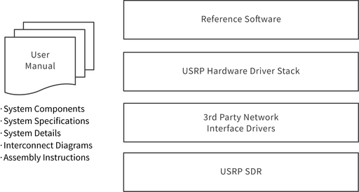
The Open Architecture for Radar and EW Research allows engineers to quickly scale from software simulation to hardware demonstration. It features direct conversion RF sampling (200 MHz instantaneous bandwidth) with NI USRPs for L-band, S-band, and C-band radar applications, enabling coherent operation through shared local oscillator (LO) , PPS, and 10 MHz reference clock signals.
The architecture features the following components:
- User manual, bill of materials, and interconnect diagrams that describe how to set up a system with up to 32 channels of Rx-Rx and Tx-Rx synchronization.
- Reference library that contains functions to configure and control the USRP N321s and USRP N320s to maintain phase coherence between multiple channels.
- Reference library that contains functions to configure and control the USRP N321s and USRP N320s for high-rate data transfer from multiple channels to memory or storage.
- C++ examples that demonstrate how to use reference library functions to configure and control a multichannel system.
- Documentation that lists installation and configuration information, best practices, and known issues encountered during development and validation of an 32x32 system. nxn refers to systems where n is the number of transmit and receive channels.
- Documentation that lists performance benchmarks with validated results for systems with up to 32 channels for the following specifications:
- o Synchronization between 32 Rx-Rx channels and 32 Tx-Rx channels.
- o Streaming IQ data from 32 channels to a server for further processing.
- Bill of materials for systems with up to 32 channels.
The reference architecture demonstrates waveform generation from file using RFNoC replay blocks.
Hardware Overview
The reference architecture uses USRP N321s and USRP N320s that scale from 2 to 32 phase-coherent transmit and receive channels.
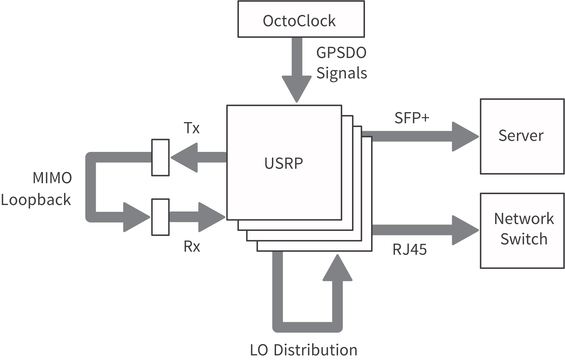
The following diagram provides an overview of the topography of the connections and primary hardware components.
For a complete list of required hardware for the Open Architecture for Radar and EW Research, refer to the bill of materials in the <REFARCH>/docs/ folder, where <REFARCH> is an alias for the following GitHub file folder location:
https://github.com/EttusResearch/refarch-multich
Required NI/Ettus Research Hardware
This section describes the NI/Ettus Research products required for generating and acquiring RF signals as well as the synchronization signals — PPS, 10 MHz, and Local Oscillator (LO) — shown in Figure 3:
- USRP N321 — Networked software-defined radio with 2-channel RF front end and 250 MSample/s on both Tx and Rx. Features a power splitter for LO distribution, 10 MHz shared reference clock for coherent MIMO functionality, shared PPS for enabling shared triggering, dual 10 GbE ports for data transfer, and an RJ45 management port for device management.
- USRP N320 — Networked software-defined radio with 2-channel RF front end and 250 MSample/s on both Tx and Rx. Features LO sharing and 10 MHz shared reference clock for coherent MIMO functionality, shared PPS for enabling shared triggering, dual 10 GbE ports for data transfer, and an RJ45 management port for device management.
- CDA-2990 with GPSDO — Clock distribution device called an OctoClock that generates and distributes 10 MHz reference clock and PPS signals and features a management port.
- NI RF Torque Screwdriver and SMA Driver Bit (NI part number 780895-01) — Torque screwdriver recommended to securely tighten all connections to/from the USRPs in the system. You can also order the RF SMA Driver Bit Only (NI part number 780894-01).
Validated Hardware
Testing and deploying a system requires hardware from both NI and third-party vendors. The following component options have been validated and are recommended for most Open Architecture for Radar and EW Research systems:
- Server
- o Supermicro 4124GS-TNR — Server with dual AMD EPYC processors and 10 PCIe 4 x16 slots. Numerous PCIe lanes from the CPU support many 10 GbE connections and the PCIe processing required for high-channel-count systems.
- o Trenton Systems BAM3U — Server with Intel dual 3rd generation Xeon Ice Lake processors and 11 Gen 4.0 PCIe slots (5–x16, 6–x8). 24x DDR4-3200 ECC RDIMM slots for high-channel-count systems.
- Network Interface Cards (NIC)
- o Intel X710-DA4 — Network card that supports x4 10 GbE connections.
- o Intel E810-CQDA2 — Network card that supports two 100 GbE connections, or, with a breakout cable, x8 10 GbE connections.
- Storage
- o HighPoint SSD7505 — PCIe carrier board that holds x4 M.2 drives and supports either a software or hardware RAID configuration.
- o Sabrent 2TB Rocket 4 PLUS — NVME M.2 SSD drive that supports consecutive writes rates of over 6 GB/s.
- Power Splitter/Combiners
- o Mini-Circuits 8-Way ZN8PD1-63W-S+ — DC pass, 8-way -0°, 50 Ω, 500 MHz to 6,000 MHz power splitter/combiner.
- o Mini-Circuits 4-Way ZN4PD1-63HP-S+ — High power, DC pass, 4-way -0°, 50 Ω, 30 W, 500 MHz to 6,000 MHz power splitter/combiner.
- Cabling
- o SMA Cable, Loop Back Cable Kit (NI part number 782781-01) — Loopback cable kit includes 2 SMA-M to SMA-M cables (60 cm/2 ft) and 2 SMA-F to SMA-M Attenuators (30 dB, 50 Ohm, DC-6 GHz).
- o SFP+ Cable, 10 Gigabit Ethernet Cable w/ SFP+ Terminations (1 Meter) (NI part number 783343-01) — SFP+ cable recommended for USRPs with 10 GigE interfaces. It can be used to connect the USRP to a 10 GigE switch or network adapter.
- Rack Accessories
- o Tripp Lite Rackmount Rack Extension Bracket (B018-000-1P5) — Bracket required to mount the USRPs in a rack.
- o Z-Bracket — Bracket required to mount the USRPs in a rack to meet environmental specifications. Contact NI for more information about how to procure Z-brackets.
Software Overview
The reference software, shown in Figure 2, consists of a reference library and examples, written in C++, using USRP Hardware Driver (UHD) version 4.1. The reference software is supported on Ubuntu Linux 20.04. It demonstrates how to assemble multi-USRP systems through the UHD RFNoC API and replay block. It contains a Python-based binary int16 data file (.dat) generator and viewer. The reference software is written so it is scalable for systems beyond the validated 32x32 system.
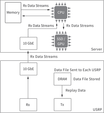
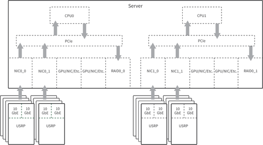
The software demonstrates a Tx-Rx loopback across a system of USRPs. To maximize Rx bandwidth, the replay block is used to reduce host processing and network traffic for Tx. Data moves through the system as shown in the following figure.
Building the System
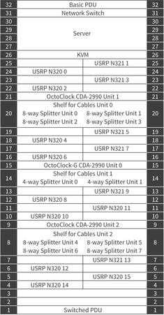
The following figure shows a 32x32 system layout. NI recommends using a rack for this system to simplify connections between the different hardware components.
System Assembly Best Practices
Adhere to the following best practices when installing, setting up, and connecting components to your system:
- While running the system in loopback, attach 30dB attenuators to all output channels to prevent damage to the USRPs.
- Arrange the equipment in the rack to optimize proper airflow. USRP N321s and USRP N320s facilitate airflow from right to left, and the server facilitates airflow from front to back. NI recommends using Z-brackets to vertically stagger installation of USRPs. Contact NI for more information about how to procure the Z-brackets.
- Position the lowest USRP in the rack a few units up from the floor to allow for adequate device connector accessibility.
- NI recommends positioning the USRPs halfway to 2/3 toward the rear of the rack to allow easier bundling of cables.
- Number and label the USRPs with serial numbers. Visit the <REFARCH>/docs/32_Channel_Template_layout_BOM_and_wiring.ods for a customizable template.
- Label the NICs and 10 GbE cables to identify each USRP connection, as described in Connecting the SFP+ Ports.
- Connect the RX LO OUT and TX LO OUT cabling from Distribution Tier of USRP N321s to the nearest USRP N320 devices, as described in Connecting the LO Distribution.
- Keep signal path of all Rx, Tx, LO, PPS, and 10 MHz signals identical, using the shortest cable possible per tier, as described in Cabling the Hardware.
- Use a calibrated torque wrench to connect all SMA connections to industry standard torque measurements.
- Periodically check all cabling to ensure a secure connection.
Cabling the Hardware
The following topics describe the connections for 8x8, 16x16, and 32x32 system connections.
- Note Ensure that you use a calibrated torque wrench for all cabling connections. NI recommends the RF Torque Screwdriver and SMA Driver Bit (NI part number 780895-01).
Connecting the RF RX-TX Ports for a MIMO Loopback
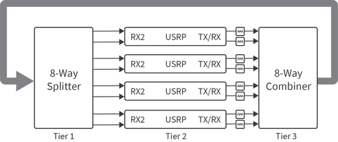
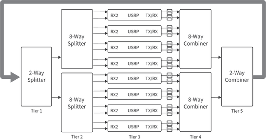
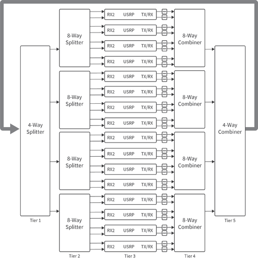
Use the MIMO loopback to validate the setup of the system and provide a baseline for synchronization calibration. Create the MIMO loopback by connecting the USRP TX/RX connectors (used for transmitting signals) to a combiner, connecting the combiner to a splitter, and the splitter to the USRP RX2 connectors (used for receiving signals).
- Note NI recommends keeping all cables in the same tier the same length to reduce skew.
The 8x8 system requires one 8-way splitter and one 8-way combiner. To set up the MIMO loopback, connect the RF 0/1 TX/RX and RX2 connectors on the USRP to an 8-way combiner and an 8-way splitter. All cables connecting between tiers, shown in the following figure, must be the same length and type.
The 16x16 system requires two 8-way splitters, one 2-way splitter, two 8-way combiners, and one 2-way combiner. To set up the MIMO loopback, connect the RF 0/1 TX/RX and RX2 connectors on the USRP to an 8-way combiner and an 8-way splitter. Then connect the two 8-way combiners to a 2-way combiner and the two 8-way splitters to a 2-way splitter. All cables connecting between tiers, shown in the following figure, must be the same length and type.
The 32x32 system requires four 8-way splitters, one 4-way splitter, four 8-way combiners, and one 4-way combiner. To set up the MIMO loopback, connect the RF 0/1 TX/RX and RX2 connectors on the USRP to an 8-way combiner and an 8-way splitter. Then connect the four 8-way combiners to a 4-way combiner and the four 8-way splitters to a 4-way splitter. All cables connecting between tiers, shown in the following figure, must be the same length and type.
Connecting 10 MHz and PPS
Connect a 10 MHz OUT connector on the OctoClock to the REF IN connector on the USRP. Connect a PPS OUT connector on the OctoClock to the PPS connector on the USRP.
The 4x4 system requires one OctoClock with GPSDO, two USRPs, and uses two 10 MHz and two PPS OUT SMA connectors. Ensure that the source selection switch is set to internal on OctoClock 0 prior to power up.
The 8x8 system requires one OctoClock with GPSDO, four USRPs, and uses four 10 MHz and four PPS OUT SMA connectors. Ensure that the source selection switch is set to internal on OctoClock 0 prior to power up.
The 16x16 system setup requires one OctoClock with GPSDO, eight USRPs, and uses eight 10 MHz and eight PPS OUT SMA connectors. Ensure that the source selection switch is set to internal on OctoClock 0 prior to power up.
Scaling to a 32x32 system requires one OctoClock with GPSDO (OctoClock 0, shown in the following figure), two additional OctoClocks (OctoClocks 1 and 2), and 16 USRPs. The source 10 MHz and PPS signals originate from OctoClock 0, which drives the OctoClock 1 and 2 inputs. OctoClock 1 and 2 each distribute all eight output 10 MHz and PPS signals to USRPs, 16 in aggregate. All cables connected from OctoClock 0 must be the same length. All cables connected to the USRPs must be the same length. Ensure that the source selection switch is set to internal on OctoClock 0, and that the source selection switch is set to external on OctoClocks 1 and 2. The selection switches must be set prior to power up.
Connecting the LO Distribution
Connect the TX LO OUT, RX LO IN, and TX LO IN connectors on the USRPs for LO distribution. While connecting the LO distribution, adhere to the following:
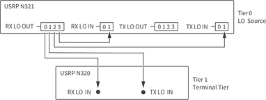
Tx and Rx must share the same LO connection. The LO sharing configuration for USRP N321s and USRP N320s in this system differs slightly from the LO sharing diagram on the Ettus Knowledge Base[1]. Distributing the LO from one channel to all other channels results in phase coherence across all channels, and there will be a constant non-zero phase offset between any two channels. This phase offset can be empirically measured and compensated for in software thus resulting in all channels being phase aligned. The overall system is phase synchronous under a wide range of conditions; refer to Synchronization for more information about measured synchronization performance.
Configure all USRPs, including the LO Source USRP, to use external LO inputs. Refer to
sync.cppin the <REFARCH>/lib/ folder for information about how the reference software configures the LOs on the USRPs.Use tiered LO signal distribution and identical cable lengths between any specific tiers.
Connect the RX LO OUT and TX LO OUT cabling from Distribution Tier of USRP N321s to the nearest USRP N320s, as shown in the following figures.
Use minimal identical cable length between tiers.
The following table lists the tiers for all system configurations.
| System | Tier(s) | USRP N321 Minimum Quantity | USRP N320 Maximum Quantity |
|---|---|---|---|
| 2x2 | LO Source (0) | 1 | — |
| 4x4 | LO Source (0), 1 | 1 | 1 |
| 8x8 | LO Source (0), 1, 2 | 2 | 2 |
| 16x16 | LO Source (0), 1, 2 | 3 | 5 |
| 32x32 | LO Source (0), 1, 2, 3 | 6 | 10 |
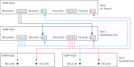
The following diagrams represent LO distribution signal connections.
The 2x2 system requires two cables of identical length. Note that you cannot combine LO signals. NI recommends that all LO distribution cables originating from the same tier are the same length.
The 4x4 system requires four cables of identical length. Note that you cannot combine LO signals. NI recommends that all LO distribution cables originating from the same tier are the same length.
For the 8x8 system, both RX LO OUT cables originating from the LO Source USRP N321 must be the same length. All RX LO OUT and TX LO OUT cables originating from the Tier 1 USRP N321 must be the same length. Note that you cannot combine LO signals.
| Cable Color in Diagram | Cable Tier | Number of Cables in Tier |
|---|---|---|
| |
LO Source Tier 0 | 2 |
| |
Distribution Tier 1, RX LO OUT | 4 |
| |
Distribution Tier 1, TX LO OUT | 4 |
For the 16x16 system, all RX LO OUT cables originating from the LO Source USRP N321 must be the same length. All RX LO OUT and TX LO OUT cables originating from Tier 1 USRP N321s must be the same length. Note that you cannot combine LO signals.
| Cable Color in Diagram | Cable Tier | Number of Cables in Tier |
|---|---|---|
| |
LO Source Tier 0 | 4 |
| |
Distribution Tier, RX LO OUT | 8 |
| |
Distribution Tier, TX LO OUT | 8 |
For the 32x32 system, both RX LO OUT cables originating from the LO Source USRP N321 must be the same length. All RX LO OUT and TX LO OUT cables originating from the Tier 1 USRP N321 must be the same length. All RX LO OUT and TX LO OUT cables originating from the Tier 2 USRP N321s must be the same length. Note that you cannot combine LO signals.
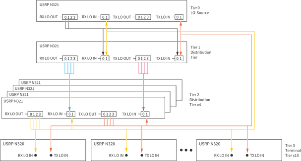
|
Connecting the USRP Management Port
Make the following RJ45 connections to configure and update the file system on the USRPs. The network port on the USRPs in this system use DHCP by default. You must either have a DHCP server running on an upstream networked device or set static IP address for each USRP.
- Connect an RJ45 cable between the server and the switch.
- Connect an RJ45 cable between the Management Port on each USRP and a port on one of the switches.
- (Optional) Connect a cable between the network switch and external internet for network management.
- Note NI recommends that you create a document for tracking USRP serial numbers with assigned network address. Visit the <REFARCH>/docs/ folder for a customizable template.
Connecting the SFP+ Ports
The server contains multiple network interface cards (NIC), each supporting multiple SFP+ ports.
Each USRP has two SFP+ ports, SFP+ 0 and SPF+ 1; however, the reference architecture assumes the use of SFP+ 0.
Connect an SFP+ cable between the SFP+ 0 port on each USRP and a port on one of the NICs in the server.
Assign each USRP to a particular network address. NI recommends that you organize your network in the following ways:
- Label the NICs and 10 GbE cables to identify each USRP connection.
- Create a document for tracking USRP serial numbers with assigned network address. Visit the <REFARCH>/docs/ folder for a customizable template.
Connecting to Power
Plug the USRPs, OctoClocks, server, and switch into the system PDU.
Setting Up and Configuring the Software
Complete the following steps to install the software and necessary dependencies on your host machine.
- Navigate to the GitHub repository, located at https://github.com/EttusResearch/refarch-multich, to get the reference software.
- Clone the repository to your computer using standard GitHub commands or download the repository directly.
- In a terminal, navigate to the top-level refarch-multich directory and issue the following command to make the setup script executable:
-
chmod +x setup_script.sh
-
- Run the script with the following command:
-
sudo ./setup_script.sh
-
The refarch-multich repository contains the following folders:
- config — Contains script files that assist with the software installation process.
- docs — Contains system bill of materials and reference architecture template.
- examples — Contains reference architecture example and configuration files.
- lib — Contains the library source files.
- tools — Contains Python-based data file generator and viewer.
Setting Up the First USRP
The following procedure references the USRP N300/N310/N320/N321 Getting Started Guide at https://kb.ettus.com/USRP_N300/N310/N320/N321_Getting_Started_Guide. Follow the procedure with the specific steps listed in this document.
- Follow the Connecting to the ARM via SSH procedure in Connecting the Device. You do not need to set up the USRPs for a serial console connection.
- Follow the procedure in Updating the Linux File System.
- Note If the procedure in Updating the file system with Mender fails, you must follow the process in Updating the files system by writing the disk image.
- For a script that will update all USRPs connected to the system, see refarch-multich-dev/config/usrp_filesystem.sh on the github repository.
- Follow the procedure in Updating the Network Configurations. Set the MTU to 9000. If you make any changes to the network configurations, NI recommends that you restart the USRP for those changes to take effect.
- Note NI strongly recommends that you create a document for tracking USRP serial numbers with assigned network addresses. Visit the <REFARCH>/docs/ folder for a customizable template. NI recommends that you assign static IP addresses for the management port IPs. This procedure is not included in this documentation.
- For a script to update the sfp1 port on all USRPs automatically, see refarch-multich-dev/config/usrp_ip_config.sh on the github repository. The host will still need to be configured manually as shown in step 5.
- Follow the Network Mode FPGA Image Update procedure in Updating the FPGA Image to update to the XG image. Use the following command to configure both SFP ports to 10 Gb links:
-
uhd_image_loader --args "type=n3xx,addr=<N3xx_IP_ADDR>,fpga=XG" - where
<N3xx_IP_ADDR>is the actual IP address of the USRP being updated; you can find this address by correlating the serial number on the device with the IP address returned by the commanduhd_find_devices. - Note For a script to update the FPGA images on all USRPs connected to the system, see refarch-multich-dev/config/usrp_image_loader.sh on the github repository.
-
- Follow the Dual 10Gb Streaming SFP Ports 0/1 procedure in Setting Up a Streaming Connection to configure the host Ethernet adapters for 10 GbE connection to the USRP.
- Note Ubuntu Linux uses Netplan to manage IP addresses of network cards (other operating systems may configure the network interfaces differently). Visit the <REFARCH>/config/ folder to find a customizable template .yaml file. The ports on the host require an IP address that matches the USRP it connects to. Once the .yaml file is configured, copy it to the
/etc/netplandirectory (overwriting01-network-manager-all.yaml, if necessary). Then use the following command to apply the network configuration: -
$ sudo netplan apply
- Note Ubuntu Linux uses Netplan to manage IP addresses of network cards (other operating systems may configure the network interfaces differently). Visit the <REFARCH>/config/ folder to find a customizable template .yaml file. The ports on the host require an IP address that matches the USRP it connects to. Once the .yaml file is configured, copy it to the
- Follow the procedure in Verifying Device Operation.
- (Optional) Follow the procedure in USRP N3xx Device Specific Operations to configure USRP settings.
Setting Up Additional USRPs
After setting up the first USRP, follow the complete procedure in Setting Up the First USRP for the remaining USRPs with the specific details listed here.
- For subsequent devices, you may choose to execute the following procedures in parallel:
- o Updating the Linux File System
- o Updating the Network Configurations — Each USRP port must be configured to have a different subnet.
- o Updating the FPGA Image
- Update the .yaml file on the host computer after configuring each remaining USRP.
Optimizing the Host System
Adjust certain settings to optimize the host system. Most of these settings are completed for you through the setup script. NI recommends that you manually configure the following optimizations:
- Note Increasing an interface's ring buffer results in more memory reserved. When setting the ring buffer make sure to monitor your memory usage. High number of interfaces can result in hundreds of GB of memory usage. A restart might be needed to clear the memory allocation.
- Increase the ring buffer for each interface by calling the following command:
-
sudo ethtool -G <interface> tx 4096 rx 4096
-
- where
<interface>is the network interface of the specific USRP; you can find this interface through the Network Manager or by calling the commandifconfig.- Note This command is executed once for each interface being used. For example, a system with 16 USRPs with 16 interfaces runs 16 times and results in ~65GB of memory usage. A script has been provided that can assist with these settings. The user is required to insert the names of the host interfaces. Refer to
nicrb.shin the <REFARCH>/config/ folder for more information. This script may need to be run after each host reboot. You can reference the interface names in the .yaml file configured in Setting Up the First USRP.
- Note This command is executed once for each interface being used. For example, a system with 16 USRPs with 16 interfaces runs 16 times and results in ~65GB of memory usage. A script has been provided that can assist with these settings. The user is required to insert the names of the host interfaces. Refer to
- Enable hyperthreading on the server. Refer to server BIOS settings for information.
- Enable C states on the server. Refer to server BIOS settings for information.
Using the Software
Getting Started Examples
Open Architecture for Radar and EW Research is built using the RFNoC API that ships with the USRP Hardware Driver (UHD).
- UHD RFNoC Examples — NI recommends that users who are new to USRP Hardware Driver or the RFNoC API begin with the following UHD RFNoC examples, located in the UHD installation folder,
uhd/host/examples:
- o
rfnoc_radio_loopback.cpp— This example uses the RFNoC API to connect an Rx radio to a Tx radio and run a loopback. - o
rfnoc_replay_samples_from_file.cpp— This example uses the replay block to replay data from a file. - o
rfnoc_rx_to_file.cpp— This example uses the RFNoC API to demonstrate the radio receiving and writing to file.
- Reference Architecture Examples — The examples, located in the <REFARCH>/examples/ folder, demonstrate synchronized Tx-Rx operation scalable from 2x2 up to 32x32 systems:
- o
iterative_loopback_singlethread.cpp— This example cycles through each Tx channel to all Rx channels. - o
multifreq_loopback.cpp— This example cycles through different frequencies and callsrfnoc_txrx_loopback.cpp. - o
rfnoc_txrx_loopback.cpp— This example demonstrates a single Tx to all Rx loopback file using a multithreaded implementation. - o
rfnoc_txrx_loopback_mem.cpp— This example demonstrates a single Tx to all Rx loopback to memory using a multithreaded implementation.
Configuration Files
The reference architecture examples use configuration files instead of input arguments to configure the application. The configuration files are located in the <REFARCH>/examples/ folder.
- Refer to the example
runconfig.cfgconfiguration file for a detailed explanation of each argument. - The reference architecture uses a multiple RAID 0 system to increase the number of parallel writes, and thus achieve higher data rates. This requires user configuration to
receivefunctions.cppin the <REFARCH>/lib/ folder before building the examples. Refer toreceivefunctions.cppfor more information.
- Note Ensure that the management address for each USRP is specified in the configuration file as demonstrated in the
runconfig.cfgexample. Not specifying a management address can lead to loss of performance.
- Note Ensure that the management address for each USRP is specified in the configuration file as demonstrated in the
Running the Examples
- Open a terminal in the build folder.
- Run an example using the
--cfgFile=runconfig.cfgcommand. For example, runrfnoc_txrx_loopback.cppby calling-
./rfnoc_txrx_loopback --cfgFile=../examples/runconfig.cfg
-
Generating Waveform Data Files
- The replay block works as a playback buffer that uses DRAM to store samples on the USRP. Refer to the importData function in
replaycontrol.cppin the <REFARCH>/lib/ folder to observe how data is sent from the host to store on the USRP DRAM. - Sample data files should contain sc16 data samples and should be a multiple of 2 samples (8 bytes) in size because the replay block records and plays back in multiples of 8 bytes. Refer to
samples_generator.pyin the <REFARCH>/tools/ folder for an example of a sine wave generation. - Use the replay example to generate a waveform. Refer to the Using the RFNoC Replay Block Knowledge Base article at https://kb.ettus.com/Using_the_RFNoC_Replay_Block for more information.
Viewing Data Files
Received data files consist of interleaved int16 IQ data (IQIQI...). Refer to the readDatFile.py example in the <REFARCH>/tools/ folder for more information about viewing data files.
Measured Performance
NI has validated the performance specifications, described in this section, using a 32x32 test system configured as described in Building the System. NI used the reference software to determine the specifications in this document.
Definitions
Warranted specifications describe the performance of the system under stated operating conditions and are covered by the system warranty. Warranted specifications account for measurement uncertainties, temperature drift, and aging. Warranted specifications are ensured by design or verified during production and calibration.
Characteristics describe values that are relevant to the use of the system under stated operating conditions, but are not covered by the model warranty.
Typical specifications describe the performance met by a majority of systems.
Nominal specifications describe an attribute that is based on design, conformance testing, or supplemental testing.
Measured specifications describe the measured performance of a representative system.
Specifications are Measured unless otherwise noted.
System Characteristics
| Transmit channel count | Up to 32 |
| Receive channel count | Up to 32 |
| RF frequency coverage | 3 MHz to 6 GHz |
| RF bandwidth | Up to 200 MHz instantaneous bandwidth per channel |
| Configuration plane | 1 GbE |
| Data plane | 10 GbE |
| Processing nodes | |
| On USRP | FPGA |
| On server | CPU |
| Data storage and streaming | |
| Format | Binary |
| Type | Complex interleaved U16 |
| Acquisition mode | Streaming, finite records |
Synchronization
Synchronization Terminology
In the context of this reference architecture, a phase-coherent system is interpreted as a system operating at the same frequency with a consistent phase relationship between any two channels in the system. Phase coherence is defined as the attribute of two or more waves where the relative phase between waves is constant during the time of the measurement.
Phase coherence performance of the test system is described using the following metrics:
- Average channel-to-channel phase skew — The average phase offset between two channels. Described by how it varies over time, or from run to run.
- Standard deviation of channel-to-channel skew — One number that describes the variation of phase offset between channels around the average skew over time, or from run to run.
- Rx-Rx — Channel-to-channel specifically referring to Rx channels.
Synchronization Methodology
Skew measurements are made based on IQ data files generated using the reference software provided as part of the Open Architecture for Radar and EW Research. The measured system uses the MIMO loopback configuration, described in Connecting the RF RX-TX Ports for a MIMO Loopback, to route signals from all Tx ports to all Rx ports with a consistent path length. To measure the phase skew, the Angle-FFT method is used, wherein the IQ data generated from each channel is measured against the relevant reference signal for each measurement. The FFT method is used to extract the frequency and phase components of each signal in the vicinity of the signal’s fundamental frequency. This information is used to determine the magnitude of the phase offset between two signals in each measurement period. To compare signals throughout their entire duration, each signal is split into shorter measurement windows in which the instantaneous phase is calculated using the method described above.
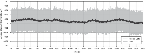
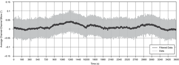
Phase Coherence One-Hour Stability[2]
Measurements are valid under the following conditions:
- Configured carrier frequency: 2 GHz (S-band/L-band)
- Configured baseband stimulus: 500 kHz sine wave, continuously transmitted for 1 hour, sampled at 6.25 MSample/s at receiver (250 MSample/s clock rate with decimation rate of 40)
- Measurement window: 4 ms (2,500 samples)
- Configuration:
- o Single device: Stimulus simultaneously received at two Rx channels on the same USRP
- o System: Stimulus simultaneously received at two Rx channels on arbitrary separate USRPs
- Analysis:
- o Where µn is average skew between two channels in measurement window n
- o µn – µ0 is the average skew relative to t0
- o Range{µ0, µ1, … , µN} is the range
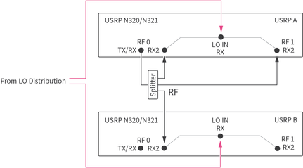
- Note Rx channels on the same USRP internally share the RX LO input to that device as shown in the following figure.
| Range, single device | 0.139° |
| Range, system | 0.167° |
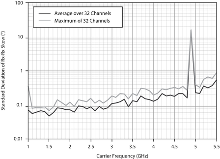
Short-Term Rx-Rx Phase Coherence[3]
Measurements are valid under the following conditions:
- Sample data generation: 32 Rx receiving simultaneously at each carrier frequency
- Carrier frequency range: 1.0 GHz to 5.5 GHz, steps of 100 MHz
- Configured baseband stimulus: 500 kHz sine wave, continuously transmitted for 56 µs, sampled at 250 MSample/s
- Measurement window: 8 µs (2,000 samples at 250 MSample/s)
- Analysis:
- o Where µnx is the average skew between channel n and reference channel in measurement window x
- o sdn = σ{µn0, µn1,…, µn6} is the standard deviation of average skew for channel n using all measurement windows
- o Average over 32 channels is µ{sd1…}
- o Maximum of 32 channels is max{sd1…}
Repeatability of Rx-Rx Phase Coherence
Measurements are valid under the following conditions:
- 10 runs
- Transmit from one Tx to all 32 Rx, repeat 32 times, once with each Tx
- Configured carrier frequency: 2 GHz
- Configured baseband stimulus: 56 µs, sampled at 250 MSample/s
- Measurement window: 8 µs (2,000: samples)
- Analysis:
- o Where mnx is Rx n-to-Rx 0 average skew in run x
- o sdn = σ{mn0, mn1, … mn9} is the standard deviation from run to run of Rx-Rx skew for channel n
- o rn = Max(Abs({mn0, mn1, … mn9} - mn0)) is the range from run to run of Rx-Rx skew for channel n
- o µ{sd1, sd2,…,sd32} is the system average standard deviation of Rx-Rx skew
- o Maximum{sd1, sd2,…,sd32} is the system maximum standard deviation of Rx-Rx skew
- o µ{r1, r2,…,r32} is the system average range of Rx-Rx skew
- o Maximum{r1, r2,…,r32} is the system maximum range of Rx-Rx skew
Resetting Session between Runs[4]
| Run-to-run, standard deviation of channel-to-channel skew (sdn) | |
|---|---|
| Average over 32 channels | 0.021° |
| Maximum of 32 channels | 0.145° |
| Range of average channel-to-channel skew over 10 runs (rn) | |
| Average of 32 channels | 0.070° |
| Maximum of 32 channels | 0.483° |
Resetting Configuration between Runs[5]
- Note In each run analyzed here, the carrier frequency is 2.0 GHz. Users must recharacterize channel-to-channel skew when using different carrier frequencies, because average channel-to-channel skew in the system deviates by >>1° per channel. This was tested using a 32x32 MIMO loopback and sweeping carrier frequency from 1.0 GHz to 5.5 GHz.
| Run-to-run, standard deviation of channel-to-channel skew (sdn) | |
|---|---|
| Average over 32 channels | 0.025° |
| Maximum of 32 channels | 0.066° |
| Range of average channel-to-channel skew over 10 runs (rn) | |
| Average of 32 channels | 0.067° |
| Maximum of 32 channels | 0.169° |
Streaming
Streaming to Memory Data Transfer Rate[6]
Measurements are valid under the following conditions:
- Configured frequency: 2.5 GHz (S-band)
- Configured stimulus: Single-tone
- Number of channels: Varied
- Duration: Single run, 10 s
| Streaming Rate (MSample/s per Channel) | Number of Channels | Measurement Time (s) |
|---|---|---|
| 33.33 | 32 | 10 |
| 50 | 16 | 10 |
| 122.88 | 8 | 10 |
- Note For more information about supported sampling and master clock rates refer to the USRP N300/N310/N320/N321 Getting Started Guide at https://kb.ettus.com/USRP_N300/N310/N320/N321_Getting_Started_Guide.
Streaming to Disk Data Transfer Rate[7]
Measurements are valid under the following conditions:
- Configured frequency: 2.5 GHz (S-band)
- Configured stimulus: Single-tone
- Number of channels: Varied
- Duration: Single run, 10 s
| Streaming Rate (MSample/s per Channel) | Number of Channels | Measurement Time (s) |
|---|---|---|
| 33.33 | 32 | 10 |
| 50 | 16 | 10 |
| 62.5 | 8 | 10 |
Appendix: Creating High-Channel-Count Systems
NI tested and configured the Open Architecture for Radar and EW Research for a 32x32 system. It is possible to build a 64x64 (or greater) system.
Connection Considerations for High-Channel-Count Systems
When the system channel count increases to 64 channels and greater, consider the following:
- The MIMO loopback, 10 MHz and PPS, and LO distribution connections require additional tiers.
- Drift increases for typical measurements.
LO Distribution for High-Channel-Count Systems
Refer to Connecting the LO Distribution for information about LO distribution connections and best practices.
The following table lists the tiers for the 64x64 system configuration.
| System | Tiers | USRP N321 Minimum Quantity | USRP N320 Maximum Quantity |
|---|---|---|---|
| 64x64 | LO Source (0), 1, 2, 3 | 11 | 21 |
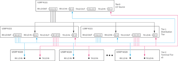
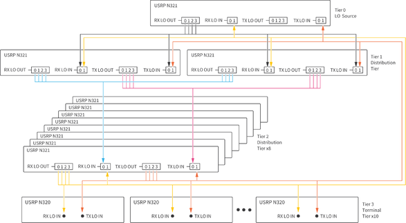
The following diagram represents LO distribution signal connections.
For the 64x64 system, all RX LO OUT cables originating from the LO Source USRP N321 must be the same length. All RX LO OUT and TX LO OUT cables originating from the Tier 1 USRP N321s must be the same length. All RX LO OUT and TX LO OUT cables originating from the Tier 2 USRP N321s must be the same length. Note that you cannot combine LO signals.
Additional Resources
Related Documentation
Refer to the following documents to learn more about the Open Architecture for Radar and EW Research, software, and hardware components:
- GitHub repository — Contains the system bill of materials and reference software example and library files needed to set up, install, and run your Open Architecture for Radar and EW Research system. Visit https://github.com/EttusResearch/refarch-multich .
- USRP N300/N310/N320/N321 Getting Started Guide — Describes how to install software, how to set up your USRP, and confirm that your device is operating properly. Visit https://kb.ettus.com/USRP_N300/N310/N320/N321_Getting_Started_Guide.
- N320/N321 specifications — Lists specifications for the USRP N321 and USRP N320. Visit https://kb.ettus.com/N320/N321.
- USRP Hardware Driver and USRP Manual — Describes how to use the USRP N321 and USRP N320 and how to use the API to connect to devices through your own software. Visit https://files.ettus.com/manual/index.html.
- USRP N320/N321 LO Distribution — Describes LO distribution connections and commands. Visit https://kb.ettus.com/USRP_N320/N321_LO_Distribution.
Training Resources
- Using Open-Source Tools with USRP Hardware for SDR Applications — Visit learn.ni.com, select View Library, and search for
using open-source tools with USRP. - Open-Source SDR Knowledge Base — Visit https://kb.ettus.com/Knowledge_Base.
- SDR-Academy Informal Getting Started Videos — Visit the SDR Academy at www.ettus.com/support/sdr-academy/.
- RFNoC Workshop from GRCon 2020 — Visit https://kb.ettus.com/Training_Workshops to find RFNoC video links and workshop materials.
Footnotes
- ↑
The LO Distribution Knowledge Base article at https://kb.ettus.com/USRP_N320/N321_LO_Distribution does not show one LO signal shared across Tx and Rx.
- ↑ Stability reports variation in the value of average channel-to-channel phase skew over a long (>>1 s) duration.
- ↑ Short-term describes variation in channel-to-channel phase skew over a short duration (<100 µs).
- ↑ A USRP session is a period in which communication links between chips in the USRP are established and not changed. Session reset is accomplished by restarting the reference software for each run.
- ↑ A USRP configuration is a period in which the digital path within the USRP is configured and not changed. Configuration reset is accomplished by changing carrier frequency from 2.0 GHz to 2.1 GHz and back to 2.0 GHz between runs.
- ↑ Streaming to memory is measured as the sustained data transfer rate without any overflows.
- ↑ Streaming to disk is measured as the sustained data transfer rate without any overflows.


